QIRF Operation And Maintenance Manual
QIRF Operation Manual May. 01, 2012
85050-301-000 Rev C
5
1.4 Specifications
Input Power:
24VDC nominal, range 18 to 30VDC, 1.0A DC Total Max.
24VAC nominal, range 15 to 24VAC, 1.0A AC Total Max.
Fuse:
F1 on Display Board: Polyswitch 1.6A
F2 on Display Board: Polyswitch 50mA
Polyswitch device resets after the fault is cleared and power
to the circuit is removed
Sensor:
Infrared Refrigerant
Gas Detected:
User selectable: R11, R12, R22, R114, R123, R134A,
R402A, R404A, R407C, R408A, R409A, R410A, R422A,
R438A, R507A
Available on special order: R13, R14, R21, R23, R31, R32,
R41, R113, R115, R116, R125, R143a, R152, R161 …
Range:
0 to 100ppm for R123; 0 to 1000ppm for others
Accuracy:
±3% of reading
Repeatability:
±1% of full scale
Sampling:
Diffusion or Pump-through
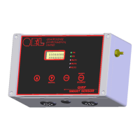
Panel Indicators:
5 Status LED’s
• RS-485 TX Status (Green)
• RS-485 RX Status (Green)
• Relay1 Status (Red)
• Relay2 Status (Red)
• Relay2 Status (Red)
Display:
2 x 8 character display c/w backlight
Keypad:
4 magnetic sensors with Magnet tool
Relays:
3 Relays SPDT, Dry contacts
• 1.0A maximum at 30 VDC (resistive load)
• 0.3A maximum at 125VAC (resistive load)
Buzzer:
80 db at 10 cm, 2700 Hz
Buzzer 1: Double-tap Intermittent
Buzzer 2: Intermittent 50% duty cycle
Buzzer 3: Continuous