Increasing Range Using an External LNA
DW3000/QM33100
Subject to change without notice | All rights reserved. © 2024 Qorvo, Inc.
APS304 Rev 1.0; Page 3 of 12 www.qorvo.com
2 Hardware Description
2.1 Overview
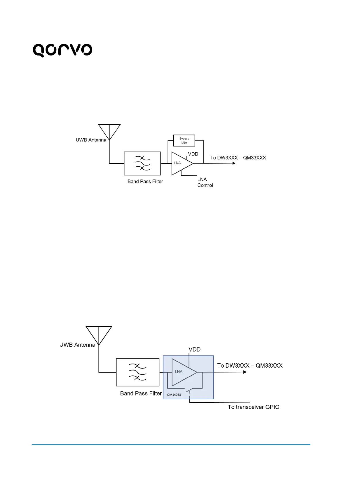
The basic scheme for incorporating an LNA into the QM33100/DW3000 receive/transmit path is illustrated in
Figure 2, below:
Figure 2: Basic scheme for incorporating an LNA
The noise figure of the LNA must be lower than the noise figure of the DW3000/QM33100. The LNA can
provide 10 to 30 dB of gain depending on the channel frequency and the amplifier used.
Adding a BPF between the antenna and the LNA is important to support Japan regulatory tests, where spurious
emissions from the transmitter are measured in conducted mode. The BPF also improves resilience to
desensitization of the receiver due to out-of-band blockers, such as Wi-Fi signals. On the other hand, the BPF’s
additional insertion loss has an obvious downside in terms of reduced Tx power headroom and receiver
sensitivity (see section 4.2). The inclusion of the BPF is therefore considered optional.
SPDT switches are used to bypass the LNA when transmitting UWB frames. Qorvo offers the QM14068 LNA
[3] with a bypass function designed and optimized for UWB channels 5 and 9. The basic scheme for
incorporating a QM14068 LNA with DW3000/QM33100 transceivers is given in Figure 3, below.
Recommended BPF components are referenced in section 2.7 of this document.
Figure 3: Basic scheme for using QM14068 LNA with DW3000/QM33100
 Loading...