EasyManua.ls Logo

QRO Technologies HF-2500DX - User Manual

QRO Technologies HF-2500DX
23 pages
Print Icon
To Next Page IconTo Next Page
Loading...
QRO HF-2500DX LINEAR AMPLIFIERQRO HF-2500DX LINEAR AMPLIFIER
INSTRUCTION MANUAL
QRO TECHNOLOGIES, INCQRO TECHNOLOGIES, INC
1117 West High Street
P.O. Box 939
Bryan, OH 43506 USA
Tel & Fax: (419) 636-2721
E-mail: sales@qrotec.com
Internet: http://www.qrotec.com
PUBLICATION DATE: October 1996
COPYRIGHT 1996 BY QRO TECHNOLOGIES, INC. ALL RIGHTS RESERVED.
THIS MANUAL OR ANY PART THERE OF MAY NOT BE REPRODUCED IN ANY FORM
WITHOUT PERMISSION FROM QRO TECHNOLOGIES, INC.

Questions and Answers

  • K
    Kevin RowlandAug 19, 2025
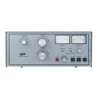
    What to do if there is no AC power in my QRO Technologies HF-2500DX?
    • J
      jennifercollinsAug 19, 2025
      If there is no AC power in your QRO Technologies Amplifier, you can check Fuse F1 or F2 on the rear panel, jumpers on Terminal Block TB1, Transformer T1, On/Off Switch SW2A or SW2B, Interlock Safety Switch SW1, and Solid State Relays SR1 or SR2 or related circuitry.
  • K
    Kimberly McmillanAug 21, 2025
    Why is there no RF output from my QRO Technologies HF-2500DX?
    • W
      wilsongabrielAug 21, 2025
      If there is no RF output from your QRO Technologies Amplifier, check for improper connections between the transceiver, amplifier, and antenna.
  • B
    Benjamin ThomasAug 23, 2025
    What to do if the multimeter is inoperative in the High Voltage Function of my QRO Technologies HF-2500DX?
    • S
      stephenmunozAug 23, 2025
      If the multimeter is inoperative in the High Voltage Function, check Resistors R210, R211, R212, R213 on the High Voltage Diode PCB, Multimeter Switch SW501A or SW01B on the Meter Switch PCB, M-1 Multimeter, Transformer T-1 Secondary, and for component failure on the HV Diode or HV Capacitor PCB.
  • C
    Catherine CannonAug 26, 2025
    What to do if the ALC is inoperative on QRO Technologies HF-2500DX Amplifier?
    • S
      Samantha WilsonAug 26, 2025
      If the ALC is inoperative, verify the connection between the transceiver and the amplifier.
  • M
    Megan MartinezAug 27, 2025
    What to do if the Grid Trip Circuit is inoperative in QRO Technologies Amplifier?
    • N
      Nicholas SmithAug 27, 2025
      If the Grid Trip Circuit is inoperative, check the Trip Reset Switch SW6 for defects.
  • L
    lauren01Aug 30, 2025
    What to do if the multimeter is inoperative in the Plate Current Function of my QRO Technologies HF-2500DX Amplifier?
    • A
      Alec SharpAug 30, 2025
      If the multimeter is inoperative in the Plate Current Function, check Resistors R311 on the LV & Bias PCB, Switch SW401A&B on the Meter Switch PCB, M-1 Multimeter, and Fuse F303 (2 Ampere).
  • E
    eharrisonSep 1, 2025
    What to do if the multimeter is inoperative in the Screen Voltage Function of my QRO Technologies HF-2500DX?
    • R
      Robert FloresSep 1, 2025
      If the multimeter is inoperative in the Screen Voltage Function, check components on the Screen Supply PCB, Switch SW401A&B on the Meter Switch PCB-510, M-1 Multimeter, and Transformer T-1 Secondary.
  • D
    Derek BowenSep 3, 2025
    What to do if my QRO Technologies HF-2500DX Amplifier will not key when transceiver is keyed to transmit?
    • K
      Kurt OneillSep 3, 2025
      If your QRO Technologies Amplifier will not key when the transceiver is keyed to transmit, check the components on the LV & Bias PCB.
  • H
    hannahmatthewsSep 5, 2025
    Why is the red power LED not functioning on my QRO Technologies HF-2500DX?
    • M
      mortonmichelleSep 5, 2025
      If the red power LED is not functioning, check the +12 VDC supply located on the LV & Bias PCB related wiring.
  • P
    Paul JohnsonSep 7, 2025
    Why is the green transmit LED not functioning on my QRO Technologies Amplifier?
    • D
      David VasquezSep 7, 2025
      If the green transmit LED is not functioning, check the +12 VDC supply located on the LV & Bias PCB related wiring.

Summary

Warranty Information

Proprietary Notice

Safety First: Always Think Safety

Unpacking and Inspection Procedures

Reshipment Instructions

Top Cover Removal Guide

Transformer and Tube Installation

Line Voltage Selection and Wiring

Introduction to the Amplifier

Operating Location Recommendations

AC Line Power Considerations

Antenna Connection

Grounding Requirements

Equipment Interconnections

Safety Interlock Switch Function

Driving Power Guidelines

Tube Precaution

Reading the Meters

Front Panel Switches and Controls

Initial Power Up Sequence

Tune Up Procedure

Adjusting Output Power with ALC

Periodic Maintenance

Troubleshooting Chart

Circuit Descriptions

Power Supply Circuit

Details the power transformer, fuses, and soft-start circuit for amplifier operation.

Plate Voltage Circuit

Explains the high-voltage rectifier and filtering circuit for plate voltage supply.

Tube Filament Supply

Describes the filament supply voltage and heating requirements for the amplifier tubes.

12 VAC Supply Circuit

Details the 12 VAC secondary winding of T2 and its use in DC supply circuits.

120 VAC Isolation Supply

Explains the 120 VAC secondary winding of T2 providing isolated supply for the 120 VDC power supply.

Control Grid Bias Circuit

Describes the circuits providing cutoff bias and transmit bias for the amplifier's control grids.

Screen Grid Bias Circuit

Explains the screen grid bias generation using a voltage doubler and zener diodes.

RF Input Circuits

Details the RF input path in standby and transmit modes, including bypass and tuning.

Tube Configuration

Describes the tube connections, RF driving power, and cooling for the amplifier's tubes.

RF Output Circuits

Explains the tuned output circuit (pi-l network), impedance matching, and harmonic suppression.

ALC Circuit Operation

Details the ALC circuit function, its control, and how it reduces overdrive.

Screen Grid Meter Circuit

Explains how screen grid current is measured using meter M-2 and shunt resistors.

PV (Plate Voltage) Meter Circuit

Describes the voltage divider and components used to measure plate voltage with meter M-1.

IP (Plate Current) Meter Circuit

Details how plate current is measured using meter M-1 and a voltage drop across a resistor.

SV (Screen Voltage) Meter Circuit

Explains the voltage divider and components used to measure screen voltage with meter M-1.

RF I;O Switching and Bias Relay Circuits

Describes the keying circuit, T/R relays, and bias relay switching.

Screen Grid Protection Circuit

Explains the circuit that protects against excessive screen grid current and its reset mechanism.

QRO Technologies HF-2500DX Specifications

General IconGeneral
Input Power100W maximum
Power Supply240V AC, 50/60Hz
CoolingForced Air
Power Output2500W PEP SSB, 2000W CW
Output Power2500W PEP SSB, 2000W CW
Input Impedance50 ohms
Output Impedance50 ohms
Gain13 dB
Harmonic Suppression-50 dB or better
IMD (3rd Order)Better than -30 dB
Frequency Coverage1.8-30 MHz