
V
Valerie HernandezSep 10, 2025
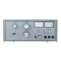
What to do if the meter lamps do not light on my QRO Technologies HF-2500DX Amplifier?
- SScott PatrickSep 10, 2025
If the meter lamps do not light, check the components on the LV & Bias PCB.
What to do if the meter lamps do not light on my QRO Technologies HF-2500DX Amplifier?
If the meter lamps do not light, check the components on the LV & Bias PCB.
What to do if the two minute warmup cycle is not functioning on my QRO Technologies HF-2500DX?
If the two minute warmup cycle is not functioning, check the components on the LV & Bias PCB.
What to do if there is no plate idle current on my QRO Technologies HF-2500DX Amplifier?
If there is no plate idle current, check the components on the LV & Bias PCB.
What to do if the plate current does not read zero in standby mode on QRO Technologies HF-2500DX Amplifier?
If the plate current does not read zero in standby mode, check the components on the LV & Bias PCB.
Details the power transformer, fuses, and soft-start circuit for amplifier operation.
Explains the high-voltage rectifier and filtering circuit for plate voltage supply.
Describes the filament supply voltage and heating requirements for the amplifier tubes.
Details the 12 VAC secondary winding of T2 and its use in DC supply circuits.
Explains the 120 VAC secondary winding of T2 providing isolated supply for the 120 VDC power supply.
Describes the circuits providing cutoff bias and transmit bias for the amplifier's control grids.
Explains the screen grid bias generation using a voltage doubler and zener diodes.
Details the RF input path in standby and transmit modes, including bypass and tuning.
Describes the tube connections, RF driving power, and cooling for the amplifier's tubes.
Explains the tuned output circuit (pi-l network), impedance matching, and harmonic suppression.
Details the ALC circuit function, its control, and how it reduces overdrive.
Explains how screen grid current is measured using meter M-2 and shunt resistors.
Describes the voltage divider and components used to measure plate voltage with meter M-1.
Details how plate current is measured using meter M-1 and a voltage drop across a resistor.
Explains the voltage divider and components used to measure screen voltage with meter M-1.
Describes the keying circuit, T/R relays, and bias relay switching.
Explains the circuit that protects against excessive screen grid current and its reset mechanism.
| Input Power | 100W maximum |
|---|---|
| Power Supply | 240V AC, 50/60Hz |
| Cooling | Forced Air |
| Power Output | 2500W PEP SSB, 2000W CW |
| Output Power | 2500W PEP SSB, 2000W CW |
| Input Impedance | 50 ohms |
| Output Impedance | 50 ohms |
| Gain | 13 dB |
| Harmonic Suppression | -50 dB or better |
| IMD (3rd Order) | Better than -30 dB |
| Frequency Coverage | 1.8-30 MHz |