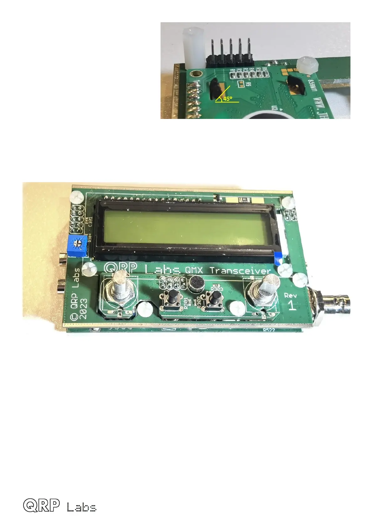
This tab needs to be bent over about 45-
degrees so that it no longer gets
obstructed by the 330uH inductor.
Now you can carefully plug together the
two circuit boards. The best way to do
this is to concentrate on getting the 5-pin
headers at the top left of the PCBs, and
the 2-pin header at the top right, to mate
accurately with each other. The rest
should fall into place by itself.
If you have taken care particularly with filing off the rough edges of the PCBs when the Display
board panel was broken out into the sub-PCBs, then you should find that the Controls PCB will fit
perfectly (though snugly) through the gap in the Display board, and it will be elevated 1.6mm (one
PCB’s thickness) above the Display board.
QMX assembly Rev 1.00e 55
 Loading...

