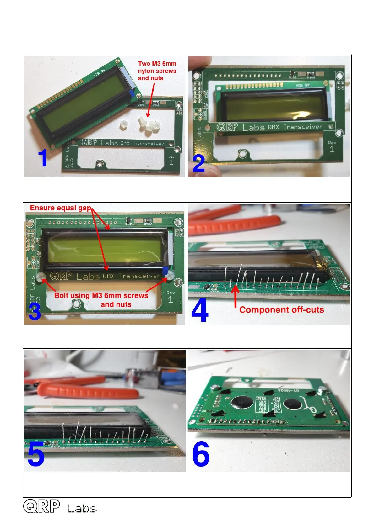
2.18 Install LCD module
Precision assembly is essential – follow the guide below carefully.
Identify the pairs of M3 6mm screws and nuts.
Fit the LCD module from behind the PCB, with
its body through the rectangular cut-out
Bolt the LCD module, ensuring equal gaps at
top and bottom; tighten screws firmly.
Drop component off-cuts through the 16 holes,
their bottom ends sitting on the bench
Solder the component off-cut wires to the top of
the PCB and trim (cut) the excess wire.
Turn over the PCB. Ensure the LCD sits flat on
the PCB before soldering; trim excess.
QMX assembly Rev 1.00e 47
 Loading...

