between the rows of pins is larger than the 1.6mm thickness of the PCB; this is fine too, no
problem. Try to solder quickly so as not to melt the plastic connector body.
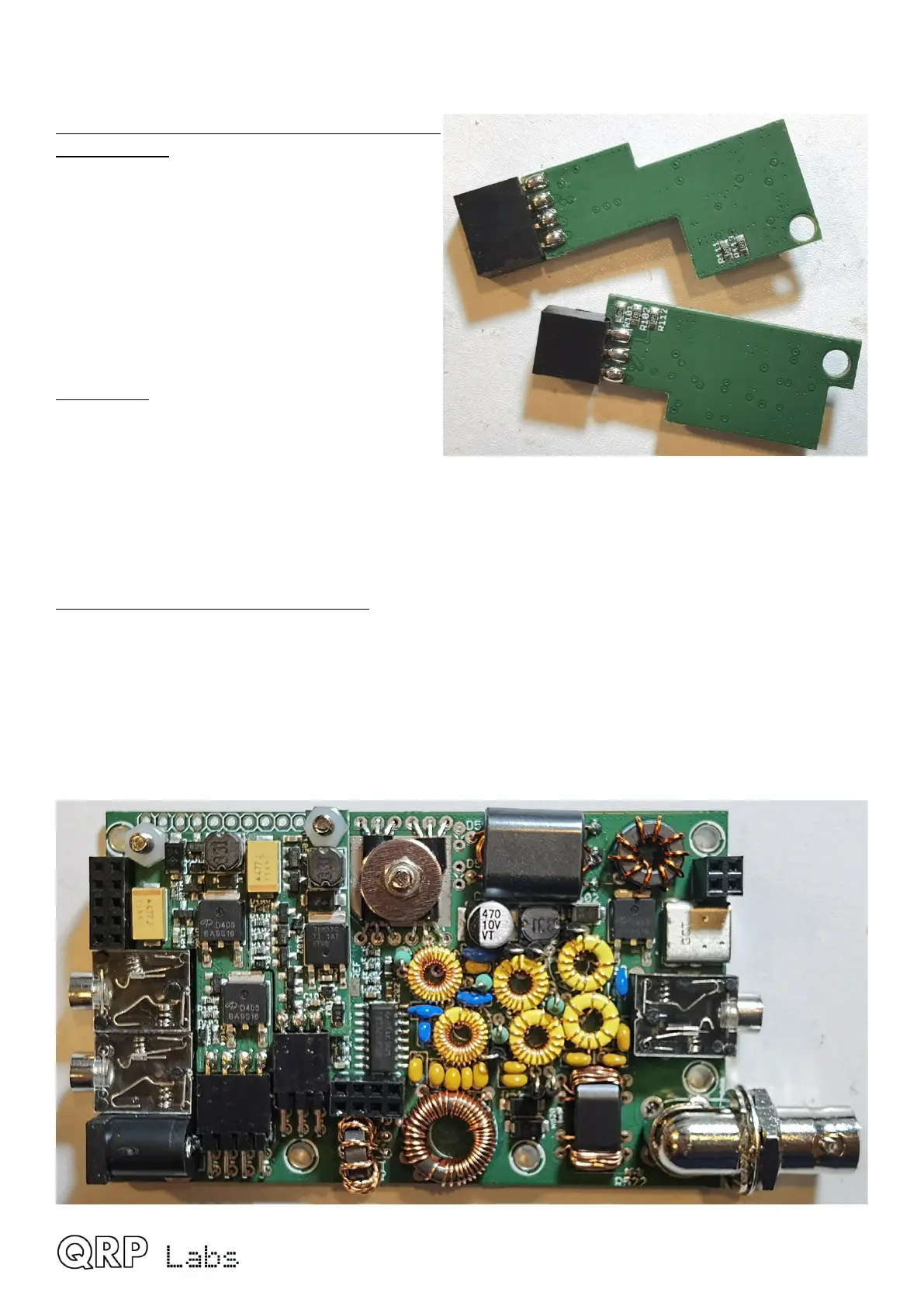
8. Remove power supply boards and solder
bottom pins: Now carefully remove the two
nylon screws that secure the power supply
boards, and unplug the power supply boards
gently. The safest way to do this is to pull on
the large AOD403 transistors with one finger-
nail. Do NOT pull on the 330-uH inductors!
Now you can solder the bottom rows of pins on
the undersides of the power supply boards.
Again – gaps are fine. Try to solder quickly so
as not to melt the plastic connector body.
9. CHECK! It is very important to check all the
connector joints, both the edge-connected
female header connectors on the power supply
boards, AND the male 90-degree headers on
the main board. Check using a jeweller’s loupe for any dry joints, poor connections, short-circuits,
solder bridges.
These boards are by far the least forgiving part of the project! Any short here, has the
potential to FRY the entire board.
10. Re-install power supply boards: Now plug in the power supply boards again, thread them
over the nylon screws, and re-install the nylon nuts, tighten securely. Be careful while tightening
the nuts, not to damage any nearby components such as the SMD components on the power
supply boards. Do not over-tighten in your enthusiasm (it’s only nylon).
The main QMX board assembly is now complete!
QMX assembly Rev 1.00e 46
 Loading...

