5. Fit connectors to boards (do not solder): The PCB pin sides of the female pin header
sockets are threaded edge-wise on the power supply board edges. Meanwhile the PCB pins of the
90-degree headers are to be inserted in the main board.
It is important to note that the 90-degree male pin header plastic body parts are NOT supposed to
sit flush on the main PCB. Neither is it necessary for the plastic parts of the female connector parts
to fit snugly next to the edges of the power supply boards. Gaps in these locations are fine and are
necessary for everything to line up square.
6. Solder 90-degree male headers to main board: Make sure that all the boards are nicely and
neatly aligned; the gap under the boards should be constant (determined by the thickness of the
two nylon “spacer” nuts. Everything should look square. Only then are you are ready to solder the
90-degree male headers (2x4-pin and 2x3-pin) to the main board. Again: do not try to force them
to sit flush on the surface of the main QMX PCB. Have them suspended off the surface 1mm or
whatever, such that the power supply boards sit level. If you have an adjustable iron: lower the
temperature. Solder quickly so as not to melt the plastic of the connectors.
Be careful not to damage nearby SMD components or create any shorts or solder bridges! Inspect
with the jeweller’s loupe! The pin header pin that is nearest to the +12V pin of the DC power
connector is NOT supposed to be connected. If you create a short there, you WILL destroy the
entire board.
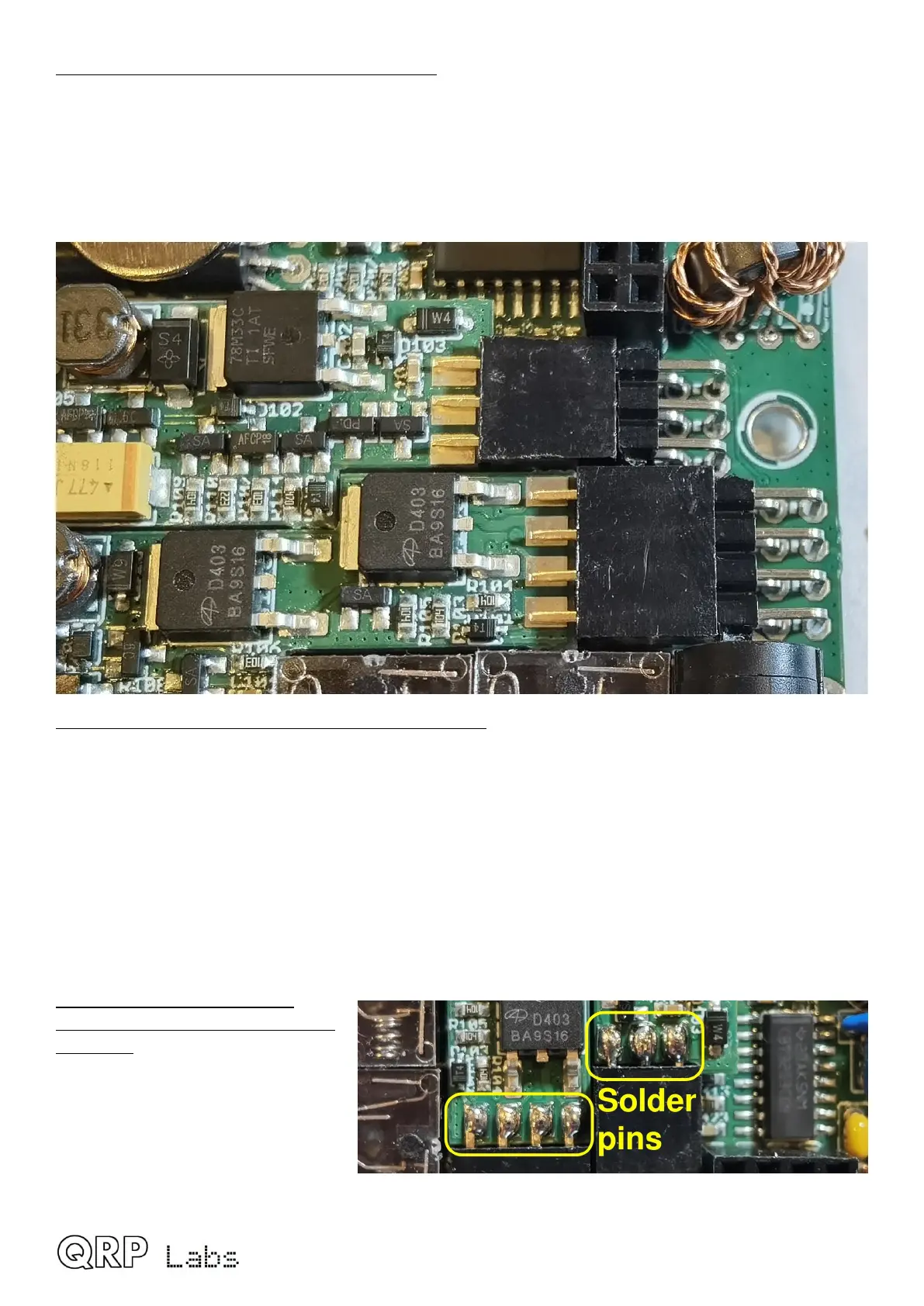
7. Solder top side of power
supply board “edge connector”
headers: The two female pin
header connector sockets fitted
edge-on at the power supply board
edges can now be soldered on the
top sides. The bottom sides are not
accessible at this point. Note that
there can be gaps because the gap
QMX assembly Rev 1.00e 45
 Loading...

