The document is a user manual for the QSA series of double propeller, three-phase electric thrusters manufactured by QS Seamaster. It provides detailed information on the product, installation, safety, usage, maintenance, spare parts, and dimensions.
Function Description:
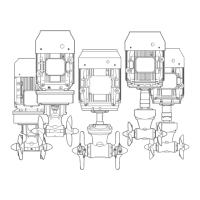
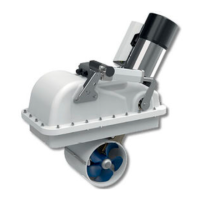
The QSA series thrusters are designed for nautical use, specifically as bow thrusters for boats. They are three-phase electric thrusters with a double propeller configuration, intended to provide thrust for maneuvering vessels. The system includes an AC motor, a gearleg, propellers, and an inverter for power control. The thrusters are designed to assist with docking and other low-speed maneuvers by providing lateral thrust.
Important Technical Specifications:
The QSA series offers a range of models with varying specifications, categorized by their thrust capacity, tunnel diameter, motor power, voltage, and suitability for different boat lengths.
- Propeller Configuration: All models feature a double propeller system. Some models use contra-rotating plastic propellers (e.g., QSA240250, QSA450386, QSA520386), while others use contra-rotating NIBRAL (Nickel Bronze Aluminum) propellers (e.g., QSA300300, QSA320300, QSA360300, QSA900513, QSA1100513).
- Tunnel Diameter: Available tunnel diameters include 250 mm (9" 27/32), 300 mm (11" 13/16), 386 mm (15" 13/64), and 513 mm (20" 13/64).
- Motor Type: Primarily two-pole electric motors, with some larger models (QSA900513, QSA1100513) utilizing four-pole electric motors.
- Motor Power: Ranges from 15 kW (e.g., QSA240250) up to 75 kW (QSA1100513).
- Voltage: All listed models operate at 400/690 V.
- Thrust: Ranges from 240 kgf (529 lbs) for the QSA240250 to 1100 kgf (2425 lbs) for the QSA1100513.
- Limit Thickness Values of the Tunnel: Specifies the acceptable thickness of the boat's hull where the tunnel is installed, varying by model (e.g., min. 6.5 mm - max 11 mm for QSA240250; min. 12 mm - max 22 mm for QSA750513 and larger).
- Boat Length Suitability: The manual provides a recommended range for boat lengths, from 18-22 m (59-72 ft) for smaller models to 32-48 m (105-155 ft) for larger ones. This is noted with a warning that suitability may vary.
- Weight: The weight of the thruster units ranges from 160 kg (353 lb) to 742 kg (1636 lb).
- Inverter: The system includes a VFD (Variable Frequency Drive) inverter, with power ratings corresponding to the motor power (e.g., 15KW 400V IP20 for 15kW motors).
- Operating Mode: The absorption on generators data refers to S3 operating mode (periodic intermittent duty), indicating that these thrusters are not designed for continuous use.
Usage Features:
- Start-up: The thruster is activated following the activation of a DPMS or APMS panel.
- Maneuvering: Designed to provide lateral thrust for boat maneuvering, particularly during docking.
- Intermittent Use: The thruster is not designed for continuous operation. It is equipped with protections that limit its operating time span, as detailed in the controls' manual. Bypassing these protections is strictly forbidden and voids the warranty.
- Safety Precautions:
- Ensure no swimmers or floating objects are in the vicinity before activation.
- Flammable materials must not be present near the thruster motor.
- Do not operate the bow thruster out of water for more than 10 seconds.
- During docking, avoid leaving free ropes in the water to prevent them from being sucked into the propellers.
Maintenance Features:
- Periodic Checks: QS Seamaster® thrusters are made of sea-resistant materials, but periodic removal of deposits from outer surfaces is essential to prevent corrosion and maintain efficiency.
- Annual Dismantling and Inspection: Recommended annually, including:
- Cleaning propellers, tunnel, and gearleg.
- Replacing anodes (more often if needed).
- Replacing damaged or worn-out propellers.
- Checking the tightness of all screws.
- Ensuring no water seepage inside.
- Checking electrical connections for tightness and absence of oxidation.
- Checking battery conditions.
- Removing graphite residues from normal motor brush use.
- Oil Seals: Periodic checking and replacement of oil seals are recommended based on usage.
- Anodes and Sealings: It is explicitly warned not to paint the anodes, sealings, and the gearleg's shafts where the propellers are lodged.
- Gearleg Flange Disassembly (Ø386 example): Instructions are provided for disassembling motor components (1-2-3-4-5) and detaching the gearleg flange (10) from the tunnel using M12x100 screws in specific cone-shaped holes.
- Oil Tank: The oil tank must be positioned above the waterline (at least 20% of the distance 'd' from waterline to tunnel center) to ensure sufficient overpressure of oil in the gearhouse. It should be filled with gear oil type GL-5. The pipe must be positioned correctly to prevent a "siphon" effect, and the tank must always be in a vertical position.
- Propeller Fitting: Detailed steps for inserting drive pins, assembling propellers, fixing them with self-braking nuts, and locking anodes with building adhesive (e.g., Loctite). After assembly, ensure propellers are exactly centered in the tunnel.
Installation Requirements:
- Professional Installation: Strongly recommended to entrust installation to a professional due to the complexity and technical competence required. The shipyard is responsible for preparing and positioning the tunnel in the hull.
- Support Base: The thruster should be installed with a support base, and the motor comes with support feet. The support must be dimensioned to withstand the weight and power of the unit.
- Alignment: Correct alignment between the drive axle and the gearbox shaft is crucial. The distance (D) between the tunnel centerline and the motor support must allow this alignment. The angle between the two shafts (gearbox and engine) must not exceed +/- 1.5 degrees.
- Tunnel Design:
- Rounded ends of the tunnel are recommended to limit turbulence and cavitation, improving thrust performance and reducing noise.
- An indentation or deflector in the rear/front part of the tunnel is advised to limit resistance caused by water flow when the boat is moving.
- If the tunnel is near the waterline, a grating with vertical and large meshes is advisable to prevent floating objects from entering while minimizing thrust contrast.
- Tunnel Positioning:
- Optimal positioning is in the bow, as low as possible, and at a distance from the waterline of at least 0.75 times the tunnel diameter.
- To avoid propeller cavitation, the tunnel must be positioned as low as possible.
- The lever effect is proportional to the distance between the boat's barycenter and the tunnel's position. Position B (further from barycenter) is preferred for greater lever effect.
- Tunnel length should ideally be 3-4 times the tunnel diameter, with a minimum of 1.5 times and an acceptable maximum of six times the tunnel diameter to limit efficiency loss.
- Hole Drilling: Use the provided drilling template and flange to mark and drill holes precisely at the halfway point of the tunnel. Ensure no resin residues in the contact area between the flange and tube to prevent misalignment.
- Sealing: Apply silicone for nautical use around the contact point between the flange and tube for water protection.
- Lubrication: Grease the terminal parts of the gearleg shaft and motor shaft during assembly.
- Electrical Connections: Use shielded cables to connect the inverter to the motor.
- Propeller Orientation: The bow thruster must be installed with the RH (right-hand) propeller on the right-hand side of the gearleg.