11
TD-001536-01-A
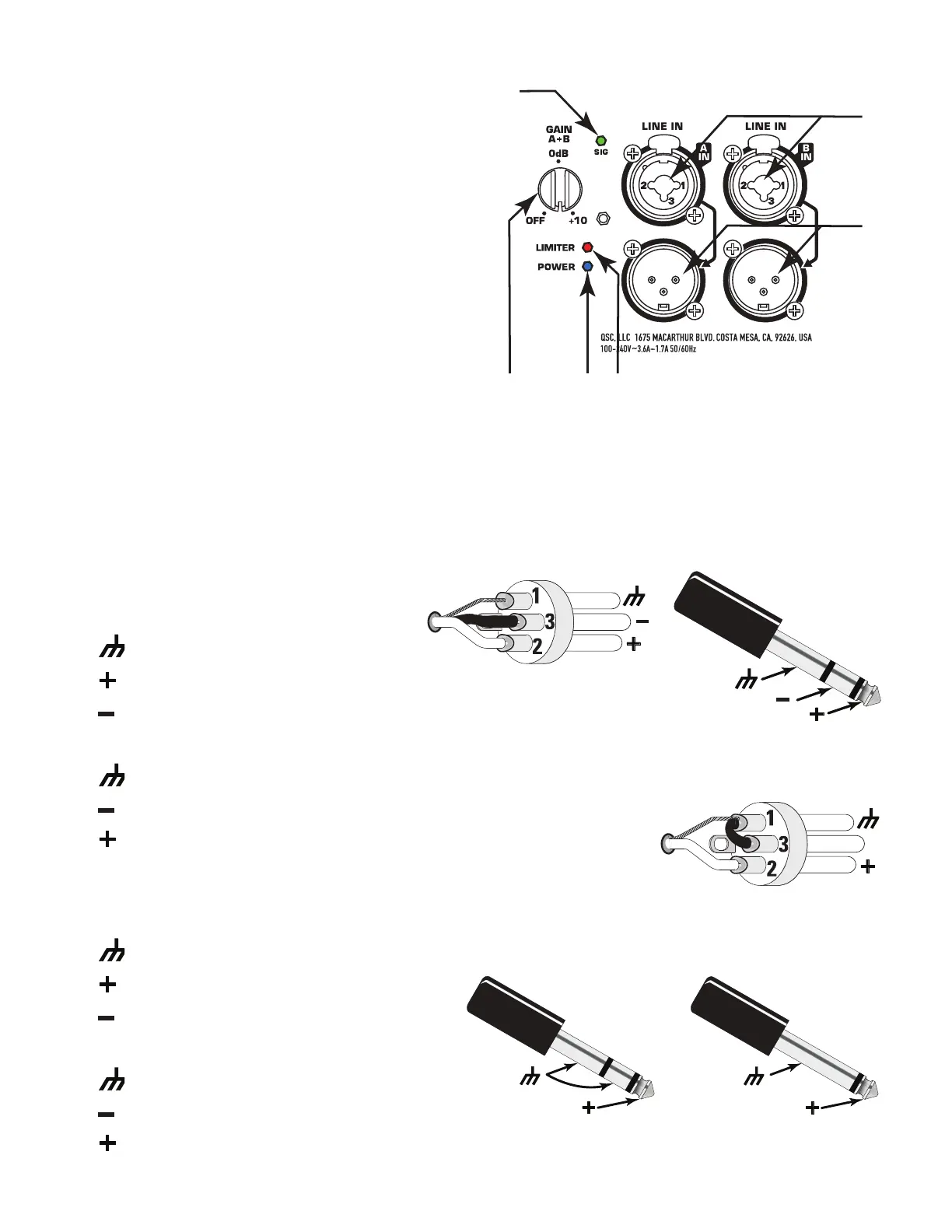
Inputs and Outputs
The KS212C amplifier has two separate female combination
XLR/1/4” Phone Jack inputs, and two corresponding
pre-gain pass-through male XLR outputs.
Refer to Figure 9
1. SIG LED – When illuminated (green), it indicates a signal is
present for Input A and/or B. If this LED is not illuminated,
the input signal is missing or too low to detect.
2. IN A/B – Combination XLR – 1/4” Phone Jack connector.
Balanced XLR and 1/4” input. Accepts line-level,
balanced or unbalanced inputs.
3. Channel A and B pass-through output connectors. The
signal here is the same as the input signal on Channel
A and B. Use these to daisy-chain loudspeakers or to
provide the signal to other audioequipment.
4. LIMITER LED – Illuminates (red) when the built-in limiter
is activated to protect and avoid damage to the amplifier or loudspeaker. If the signal level at any frequency is too
high, or the amplifier is too hot, the limiter is activated and the LED is illuminated.
5. POWER LED – Illuminates (blue) when power is applied to the unit and the ON/OFF switch is in the ON position.
6. GAIN knob – Sets the sensitivity of both Input A and B. Controls the signal level sent to the amplifier.
Balanced Inputs
Connect the XLR plug as shown in Figure 10.
1. Shield (ground)
2. Positive
3.
Negative
Connect the TRS plug as shown in Figure 11. Do not use a TS 1/4” jack for balanced input.
1.
Shield (ground)
2. Negative
3. Positive
Unbalanced Inputs
Connect the XLR plug as shown in Figure 12. (Jumper pins 1 and 3.)
1. Shield (ground)
2. Positive
3.
Negative
Connect the TRS or TS plug as shown in Figure 13.
1.
Shield (ground)
2. Negative
3. Positive
— Figure 9 —
PUSHPUSH
2
3
1
— Figure 10 —
— Figure 11 —
— Figure 12 —
— Figure 13 —
TRS TS
 Loading...