5
TD-000347-00-B
Connections
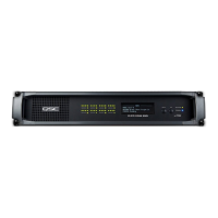
AC Power Cord
Insert the molded receptacle of the AC power cord into the AC power inlet on the back of the Q-Sys product.
(Figure 1) Plug the AC line connector into an AC outlet. The power supply on the Q-Sys Cores accepts 100 — 240
V, 50 — 60 Hz. If a different type of IEC power cord is required than that supplied with the product, consult QSC’s
Technical Services Group.
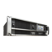
Q-Sys™ Network
Connect one end of a data communications cable (CAT-6 rating or better) terminated with an RJ45 plug into the
LAN A (and optionally LAN B) receptacle on the rear panel of the Q-Sys product. Ensure that the lock tab on the
cable engages with the RJ45 receptacle. (Figure 2)
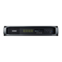
Mic/Line Inputs, Line Outputs, AES3 I/O
Several of the optional audio I/O Cards accept Euro style (also known as Phoenix) three-terminal plugs. (Figure
3) When these cards are ordered in the product confi guration a kit containing the mating plugs is included in the
carton contents. Plug the Euro terminal block plug into the appropriate input or output receptacle on the Q-Sys
Audio I/O Card’s panel face. The connection pinout is printed on the Q-Sys Audio I/O Card mounting bracket.
Refer to the illustrations in the right-hand column of this page for balanced and unbalanced connections (analog
connections only — AES3 connections always require all three conductors).
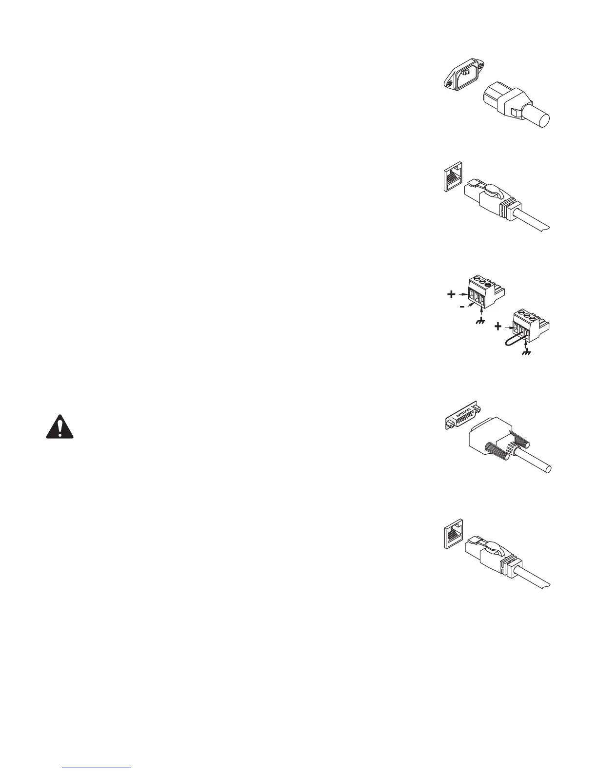
DataPorts
The Q-Sys DataPort I/O Card is intended to interface with QSC amplifi ers with v1 DataPorts. This is the all-
capable version 1 DataPort specifi cation, supported on CX, DCA, PowerLight™, PL2, and PL3 Series amplifi ers. All
DataPorts use the HD15 connector format and connect to QSC amplifi ers via data communications cables having
male HD15 connectors.
(Figure 4)
IMPORTANT:
These appear to be common VGA cables but they are not. Many off-the-shelf VGA
cables MIGHT work with satisfactory results, however it is also quite possible off-the-shelf cables will
give less-than-satisfactory results, and could even cause damage to QSC amplifi ers! The QSC DataPort
specifi cation requires that all conductors be present, as well as shielding over those conductor pairs
used for the audio channels to the amplifi er. Therefore, QSC recommends the use of QSC DataPort
cables exclusively, which are available in a variety of lengths from QSC. Use of any non-QSC DataPort
cable may void the warranty.
To connect a DataPort cable between a Q-Sys DataPort I/O Card and an amplifi er DataPort, attach the cable’s male
connectors to the HD15 ports and fi nger tighten the thumb screws on the connector.
(Figure 4)
CobraNet
The Q-Sys CobraNet I/O Card is intended to provide an interface between Q-Sys and QSC’s Basis, DCP, and third-
party CobraNet devices. The connector required is an RJ45. (Figure 5)
— Figure 1 —
— Figure 2 —
1000 BASE T
— Figure 3 —
Balanced / AES 3
Unbalanced
!
— Figure 4 —
— Figure 5 —
 Loading...