10
TD-000347-00-B
Q-Sys™ Core 250i | Core 500i | Panel Features
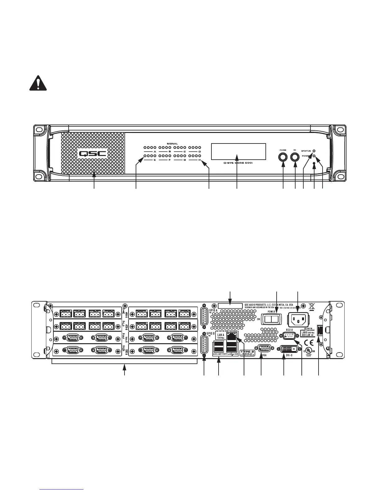
Figure 7, Figure 8, and Figure 9 show the Q-Sys Core front and rear panel features. The front panel is identical for the Core 250i and 500i. The rear
panels are shown with all eight I/O cards installed. The cards shown are intended to show all the slots in a populated condition, and not to indicate
any particular confi guration.
NOTE:
The Q-Sys hardware products are confi gured at the QSC factory per your order. At the time of order, you specify the type of
Q-Sys Audio I/O Cards to be installed in the Audio I/O bays on the Q-Sys Core. In addition, Q-Sys Audio I/O Card Kits are available for
fi eld installation by qualifi ed service personnel.
Front Panel
Rear Panel Core 250i
— Figure 7 —
1 2 4 5
6
7
8
9
3
1. Exhaust Vents
2. Audio I/O Signal Indicators
3. Card Present Indicators
4. 240 x 64 Monochrome Graphics LCD (fl ashes when the ID button in
Q-Sys Designer or Q-Sys Confi gurator is pressed.
5. Next Page Navigation Button
6. Device ID Button (locates device in Q-Sys Designer GUI)
7. Status LED (reports network health and fi rmware update status)
8. Clear Settings Paperclip Button (resets everything on the Core; does
not delete any media fi les)
9. Power On LED
1. Eight Audio I/O Bays — accepts Q-Sys Type 2 audio I/O cards
2. GPIO A and GPIO B Female DA-15 connectors for Q-Sys control I/O
3. Four Auxiliary Ports — USB host connectors
4. Q-LAN Network Port, LAN A — 1000 Mbps only, primary connection to
Q-Sys gigabit network
5. Video Out — HD-15 female connector For future use
6. Video Out — DVI female connector For future use
7. RS-232 — DE-9 male connector for serial communications
8. Q-LAN Network Port, LAN B or AUX LAN — (1000 Mbps only when
used in Q-LAN LAN B mode, 10/100/1000 Mbps when used in AUX
mode) backup connection to Q-Sys gigabit network
9. AC Main Inlet — IEC male connector with cord retainer
10. Power Switch
11. Serial Number
— Figure 8 —
2
4 5 63 7
9
1
10
8
11
 Loading...