EasyManuals Logo

QTech QSW-8200 series User Manual

Default Icon
29 pages
To Next Page IconTo Next Page
To Previous Page IconTo Previous Page
Page #14 background imageLoading...
Page #14 background image
User Manual
Chapter 1. Introduction 14
www.qtech.ru
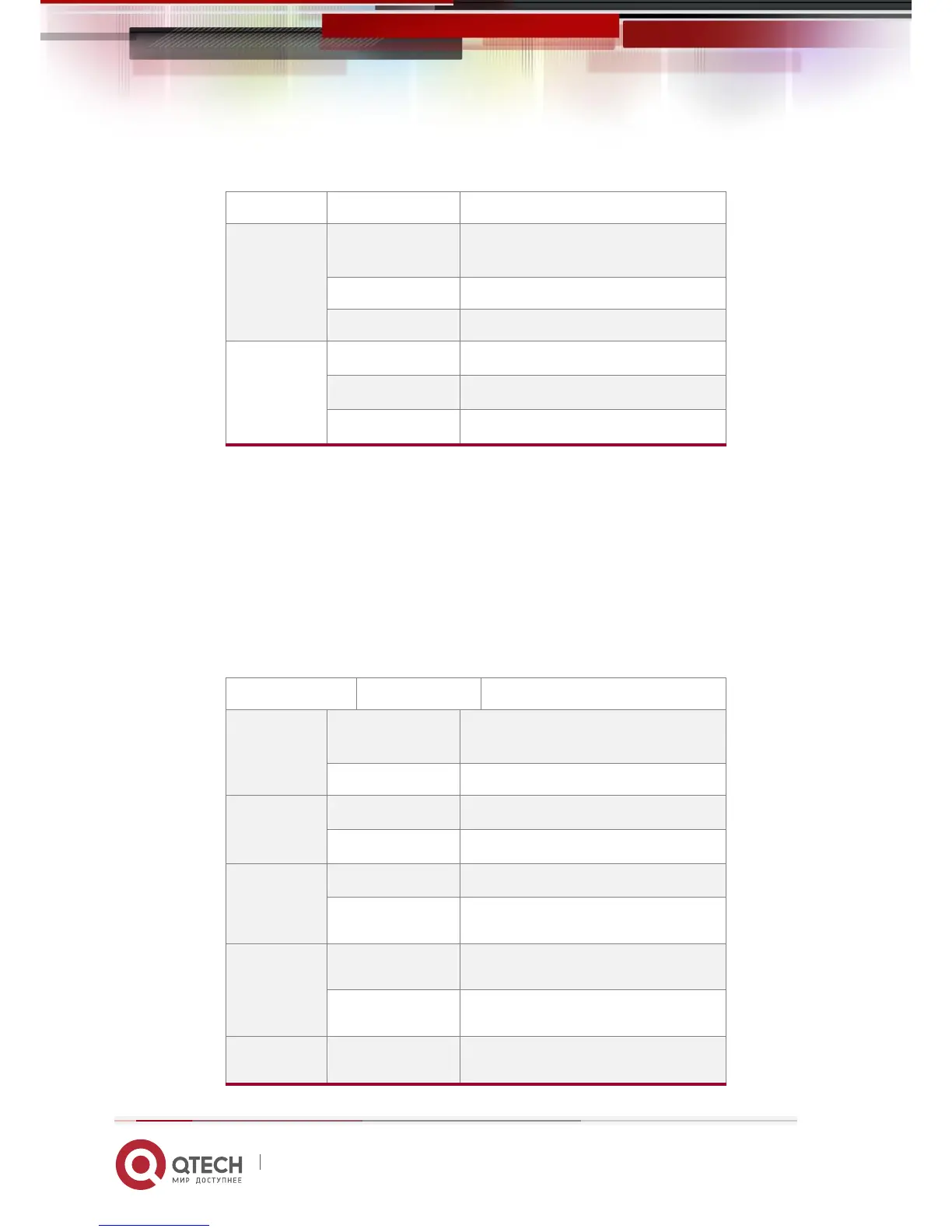
Table 1-5 SFP Port LEDs
LED
Status
Description
Left LED
On
SFP port is at link state
Off
SFP port is not at link state
Blink
There is no this state
Right LED
On
There is no this state
Off
No data is received or sent
Blink
Send or receive the data
Note: For QSW-8200-52F-AC-DC, there are four LEDs with the number from the buttom up on
the left of RJ45 linker, the number is from 1 to 4, and they correspond four ports of RJ45 linker
respectively.
The other of its kind is system LEDs, system LEDs of QSW-8200-28F-AC-DC / QSW-8200-28F-AC
and QSW-8200-52F-AC-DC are at the right of the front panel. They are corresponding name for
system LEDs with 2*4 array. They are used to show the work stateand the port state of the
extended card.
Table 1-6 System LEDs
Panel Symbol
Status
Description
PWR
On (Green)
Power is operating normally
Off
Power is abnormally
DIAG
On (Green, blink)
System is loading
On (Green)
System is operating normally
ALM
On (Green)
System is malfunctioning
Off
System is operating normally
DC
On (Green)
System is using DC power
Off
System does not use DC power
M1-1
On (Green)
Port1 of M1 is at link state

Questions and Answers:

Question and Answer IconNeed help?

Do you have a question about the QTech QSW-8200 series and is the answer not in the manual?

QTech QSW-8200 series Specifications

General IconGeneral
BrandQTech
ModelQSW-8200 series
CategorySwitch
LanguageEnglish

Related product manuals