User Manual
Chapter 1. Introduction 17
www.qtech.ru
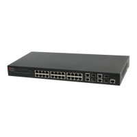
Each of the extended modules’ panel diagram is shown follows:
Figure 1-20 panel diagram of QSW-2SFP+
Figure 1-21 panel diagram of QSW-2GB
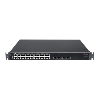
Back panel diagram of the switch with extended modules is shown in the following:
Figure 1-22 The back panel with extended modules for QSW-8200-28T-AC / QSW-8200-52T-AC
Figure 1-23 The back panel with extended modules for QSW-8200-28T-AC-DC / QSW-8200-52T-AC-
DC
Figure 1-24 The back panel with extended modules for QSW-8200-28T-POE-AC-DC / QSW-8200-52T-
POE-AC-DC
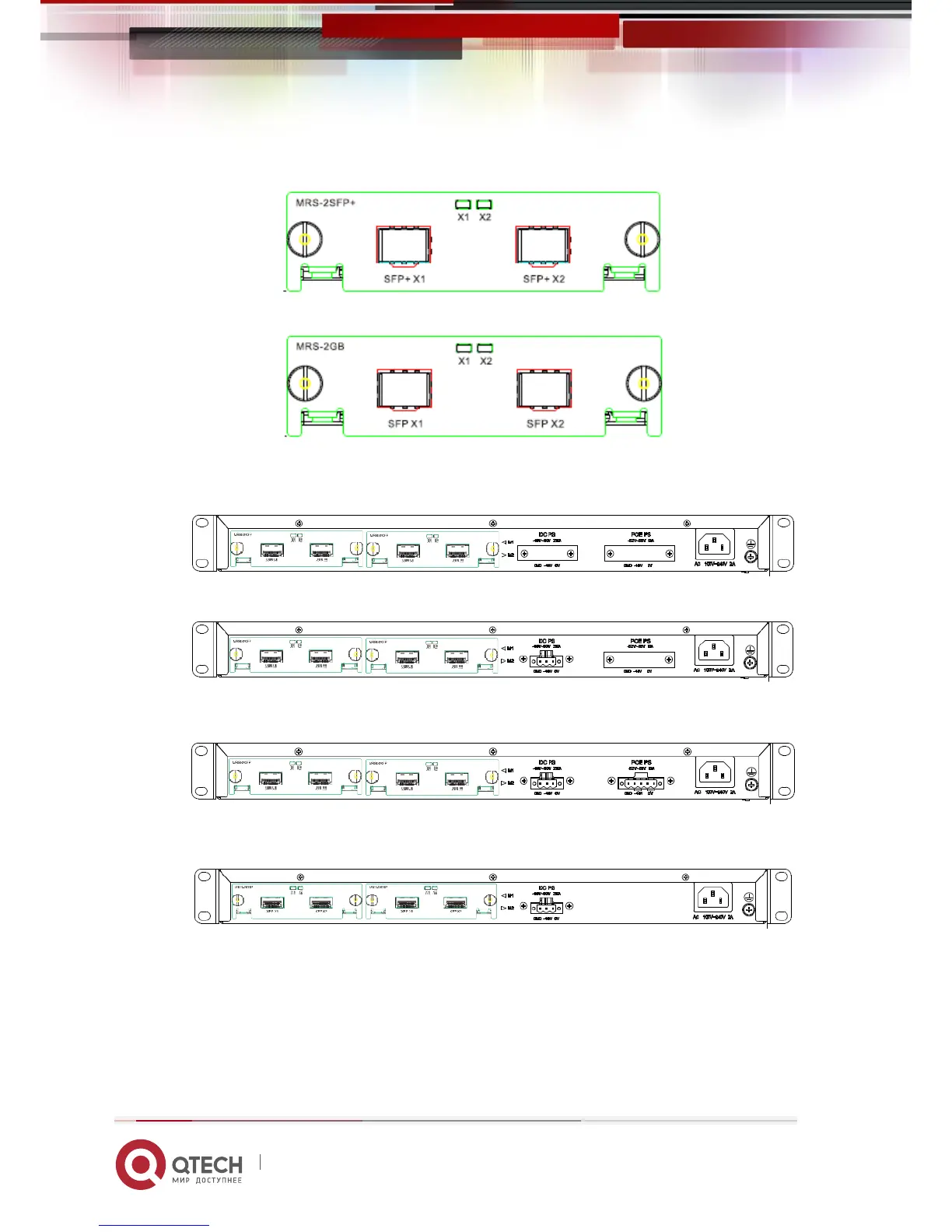
Figure 1-25 The back panel with extended modules for QSW-8200-28F-AC-DC / QSW-8200-28F-AC /
QSW-8200-52F-AC-DC
Extended module‘s LED description is the following:
 Loading...