3. SETUP
3.1 Mower Deck Assembly
Step 1. Remove the components from the shipping container:
1. The assembled deck.
2. The packaged height adjustment handle.
3. The tower assembly kits, packaged with the height adjustment handle.
Step 2. Note the Serial Number of the Deck - it is located as shown in the attached pictures!
Step 4. Prop the back of the deck up slightly – 2” – and remove the two bolts holding the rear
height adjust links going over the deck – see picture.
Step 4. Remove the deck drive shield so the drive pulleys are visible.
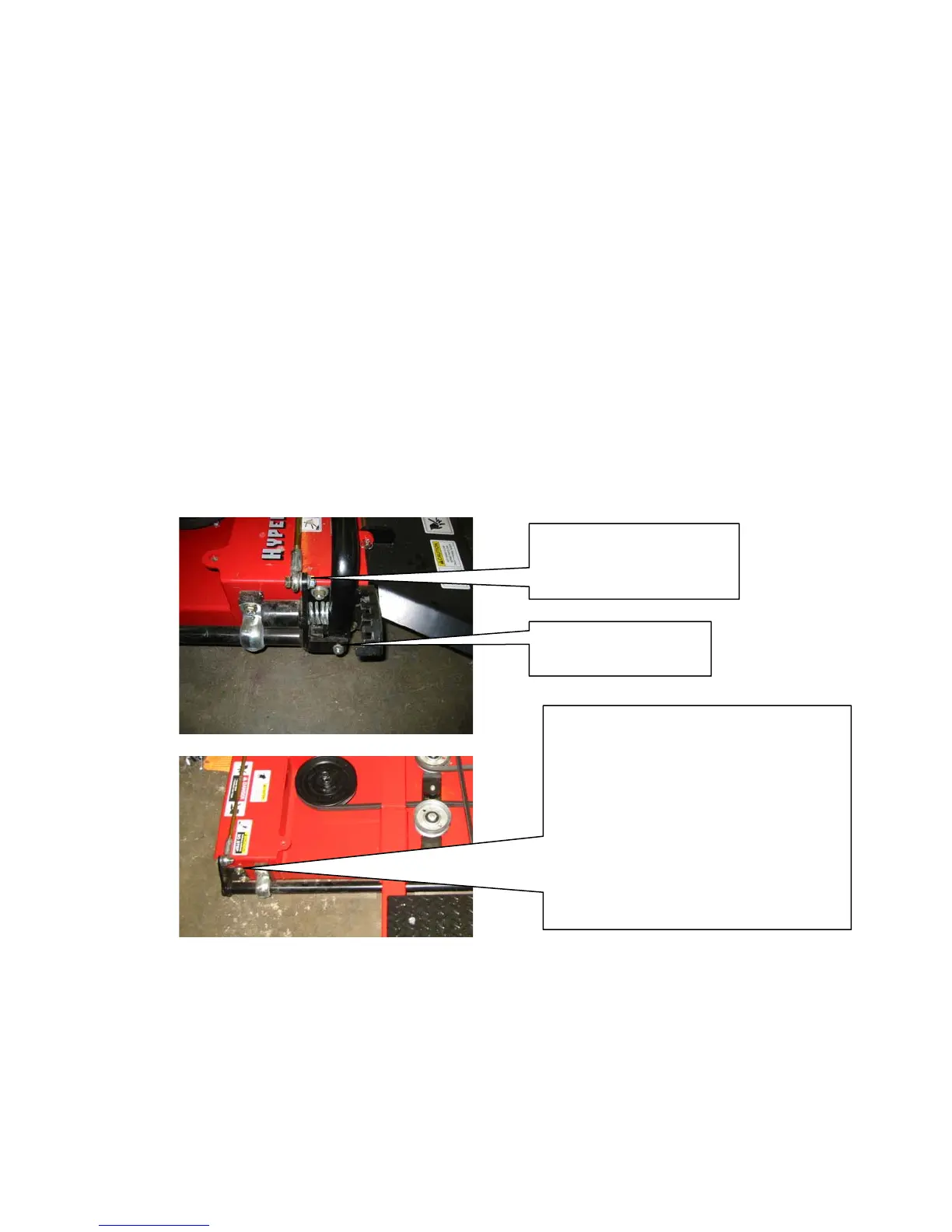
Step 5. Rotate the rockshaft backward 90° and install the height control handle using the
hardware provided and in the manner shown in the picture! Remove the tywrap holding the
spring with a pair of side cutters, then pull inwards to compress the spring and rotate the rod
upwards and into place so the height control lever contacts the height detent bracket.
Remove this hardware in
order to install the height
control lever bolt.
Height control lever
retaining bolt.
NOTE – Shown is the bracket on the LH
side of the deck which controls the
position that the horizontal hei
ht control
rod is fixed at from ri
ht to left on the
mower deck. It can be ad
usted to
position the hei
ht control handle closer
or farther from the operator once the
mower is installed on the ATV. It may
need to be ad
usted to assist in
mounting the height control lever!
Step 6. Reconnect the two bolts holding the rear of the height control links into place.
Step 7 – Install the chain restrain towers – flatten them by hinging them down, with the chains
and instruction labels attached. Lock the towers in place by spreading the center of the cotter
pin to retain the towers to the mower deck!
Step 8. Visually check that all of the safety decals are in place and readable.
The deck is now ready to be joined to the power unit.