Do you have a question about the Quantel Medical Axis II PR and is the answer not in the manual?
Details warranty conditions, required technician training, and precautions for handling the device.
Details power supply, input voltage, frequency, mains consumption, and compliance standards.
Specifies operating and storage temperature and humidity ranges for the device.
Identifies the materials used for the upper frame, lower frame, and LCD front panel.
Lists part numbers and descriptions for spare parts and accessories/options.
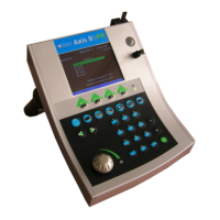
Identifies key external components and controls of the Axis II device.
Step-by-step instructions for safely opening the device casing.
Diagram showing internal components like CPU board, video interface board, and LCD screen.
Procedure for reassembling the device casing after internal access.
Illustrates the functional connections between major components of the Axis II system.
Details the components and connectors of the main CPU board.
Step-by-step guide for removing and installing a new CPU board.
Instructions for replacing the video interface board.
Procedure for removing and installing a new LCD screen.
Method to access a special service menu for advanced settings.
Procedure for calibrating the biometry probe using the test-block.
Setting the Retina Slope Test for optimal A-scan freezing.
Adjusting the dynamic scale for distortion avoidance during acquisition.
Procedure for setting the noise level for optimal image quality.
Using keycodes to enable or disable specific device features.
Steps to enable or disable the post-refractive measurement feature.
Instructions for resetting the device to factory default settings.
Detailed procedure for biometry probe calibration via test block and service mode.
Procedure for calibrating the pachymetry probe using water.
Table outlining compatibility between different software versions.
Specific requirements and steps for upgrading to software version 5.0.
Instructions for upgrading to software version 4.04.
Guidance for upgrading to older software versions.
Comprehensive guide for installing new software, including requirements and parameter backup.
Procedure for connecting the device to a computer via RS-232.
Steps to launch the QuantelProg installation utility.
Configuration of serial port and baud rate for data transfer.
Selecting the software file to be transferred to the device.
Powering on the device after connecting cables and setting parameters.
Initiating the software download process from the PC to the device.
Confirmation of successful installation and post-download actions.
Procedure for restoring saved settings after software upgrade.
Troubleshooting steps for transmission errors during printing.
Troubleshooting steps for 'No Printer Selected' errors.
Details and images of CPU boards for software versions 1.xx and 2.xx.
Comparison of first and second generation LCD screens and their compatibility.
Procedure to modify a first generation video interface board for compatibility.
Details and images of CPU and interface boards for software version 3.xx.
Visual guide to identify CPU boards for software versions 2.xx and 3.xx.
Description of the CPU board used for software version 4.xx.
Visual comparison of video interface boards for software versions V3 and V5.
Table detailing internal configuration changes across software versions.
Details software version, publishing date, revision date, and author approvals.
| Brand | Quantel Medical |
|---|---|
| Model | Axis II PR |
| Category | Medical Equipment |
| Language | English |