Do you have a question about the Quantel Medical 532NM and is the answer not in the manual?
Details warranty conditions and voiding terms for repairs and modifications.
General safety instructions for technicians and basic laser operation precautions.
Warning about hazard voltage inside the unit and protective glasses adequacy.
Caution against using controls other than specified to prevent radiation exposure.
General technical specifications including parameters, control interface, and dimensions.
Specific technical details for 532nm, 577nm, 660nm, and 810nm laser models.
Details compliance with various safety and electrical standards like IEC and FDA.
Block and wiring diagram for the SUPRA laser model.
Block and wiring diagram for the SUPRA TWIN laser model.
Block and wiring diagram for the SUPRA 810 laser model.
Block and wiring diagram for the SUPRA 577.Y laser model.
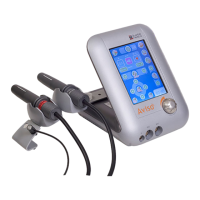
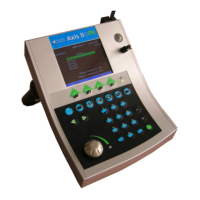
Overall views of the laser unit with numbered components for identification.
Views of the control box, including front, rear, and internal perspectives.
Internal views of the laser console and associated components.
Identifies parts and their corresponding codes for different SUPRA laser models.
Instructions for removing the laser console and control box covers.
Overview of electronic, optical, and electrical subsystems in SUPRA lasers.
General procedures for disassembling common subsystems like I/O and Power boards.
Procedures for disassembling the 532nm laser subsystem components.
Procedures for disassembling the 660/810nm laser subsystem components.
Procedures for disassembling the 577nm laser subsystem components.
Pin description and location for the CPU board (ENDO.MICRO).
Pin description and location for the Power Board (PB.NG).
Pin description and location for the I/O Board (FAR.YEL).
Pin description and location for the Power Supply unit.
Pin description and location for the 532nm Cavity Board (CAV.NG).
Pin description and location for the 532nm Injection Board (INJ.NG).
Pin description and location for the 660/810nm option Power Board.
Pin description and location for the 660/810nm option Cavity Board.
Pin description and location for the 577nm Cavity Interface Board (INT.YEL).
Procedure for calibrating the touch-sensitive screen area after transport or upgrades.
Accessing and navigating the service mode interface and screen layout.
Displays and analyzes laser output curves for diode current and cell readings.
Procedures for calibrating laser output terminals for continuous and μPulse modes.
Procedure for calibrating the aiming beam power level to specified values.
Accessing and using the production mode for advanced servicing and parameter adjustments.
Procedures for calibrating laser cavity output for continuous and μPulse modes.
Adjusting cavity component temperatures for optimal performance in the 532nm model.
Viewing laser usage statistics and accessing other parameters like power security.
Visual warnings appearing on the treatment page that disable laser shots.
Errors related to footswitch connection/state and filter connection/function.
Messages indicating power levels outside limits or external temperature issues.
Errors related to shutter, security, power supply, CPU initialization, and current.
Messages indicating that the laser cavity or a terminal is not calibrated.
Conditions and expected output parameters for a perfectly functioning laser.
Examples of correct internal cell, external cell, and diode current curves.
Examples of faulty laser output curves and their potential causes.
Description and connection of the motorized filter plug (GREEN).
Description and connection of the double-fiber adaptor plug (BLUE).
Description and connection of the doorswitch plug (RED) and remotes.
Description and connection of the footswitch plug (BLACK).
Description and wiring of the front filter and lamp remote plugs.
Diagram showing the connection of the printer cable to the laser.
Steps before software upgrade, including saving calibration data.
Instructions for connecting the PC to the laser and setting up Quantelprog software.
Process of downloading the firmware onto the laser using Quantelprog software.
Post-installation checks including touch screen calibration and setting verification.
| Brand | Quantel Medical |
|---|---|
| Model | 532NM |
| Category | Medical Equipment |
| Language | English |