11 12
ADJUSTMENTS AND SETTINGS
The Quantum amplifiers are equipped with built-in variable crossover networks
allowing you to select the crossover mode (i.e. Low-Pass/Full/High-Pass or On/Off) and
the desired crossover point. For example if you wish to drive a pair of subwoofers, you
can select the “Low Pass” setting on the amplifier to filter out high frequencies. This will
send only low frequencies to your subwoofers (see example settings below). The cross-
over point should be determined by the speakers operating range. Please refer to
speaker manufactures recommended crossover point.
FINE TUNE THE SYSTEM
Fine tune the amplifier’s input sensitivity
The gain sensitivity control for the Quantum amplifier is located on the side panel.
This gain control has been included to allow adjustment to properly match the output of
the radio. This is one of the most misunderstood adjustments. By rotating the control in
the clockwise direction, the amplifier’s input will become more sensitive and the music will
play louder. This is not a volume control and you will not get more power out of the ampli-
fier in the maximum position! It may seem to deliver more output, but actually the system
is only playing louder faster as you turn the volume control on the radio. Ideally, to
properly level match the
system the goal is to achieve maximum output from the amplifier
without distortion at about ¾ of the volume control.
To determine if the amplifier’s gain is set properly, turn the system on and slowly increase
the volume control. You should be able to use about ¾ volume before the system gets
loud but not distorting. It is very important when making these adjustments that you do not
over drive the speakers (at point of distortion) this will cause permanent damage to the
speakers. If you are unable to achieve ¾ volume before distortion you will need to adjust
gain control (in this case you would reduce the gain). The gain controls should be
adjusted very slowly. It may help to have another person to assist you by adjusting the
gain controls while you listen for distortion.
Input Level
6v .2v
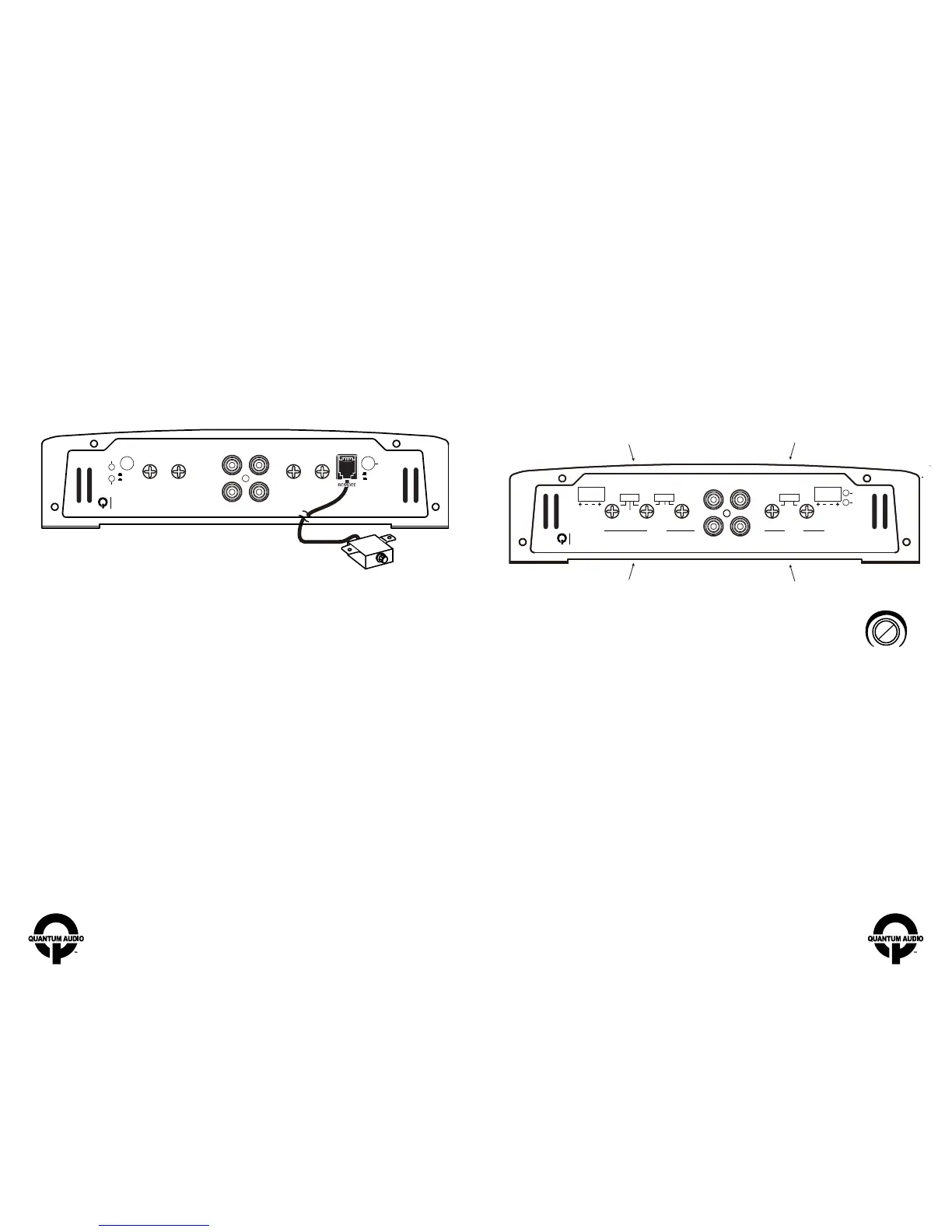
Adjust the frequency to the
desired point for speakers 1 & 2 .
Adjust the frequency to the
desired point for speakers 3 & 4 .
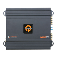
REMOTE BASS CONTROL MODULE
Before connecting the remote, it will be necessary to find a mounting location that will be
easy to access for adjustment. Once you select your mounting location, you will need to run
the control wire from the remote to the amplifier. To avoid possibility of induced noise from
the car’s electrical system (i.e. popping noises or engine noise), run the cable from the
remote to the amplifier away from the car’s electrical wiring.
POWER
Min Max
Filter selection for channel 3 & 4
Filter selection for channel 1 & 2
INPUT
LEVEL
SUBSONIC
FILTER
LOW
PASS
BASS
BOOST
Protect
Input
Sensitivity
Power
INPUT
L L
R R
OUTPUT
QE2400.1D
2400 Watt Monoblock Amplifier
20Hz 50HzMIN MAX
0.2V-2V
2V-8V
30Hz 250Hz 0dB 18dB
0
o
180
o
PHASE SHIFT
HPF HPFLPF
HIGH IN
L R
HIGH IN
L R
X-OVER X-OVERBASS EQ
INPUT
GAIN
LPF
HPF 12 6 0Full HPFFull
120Hz MIN
CH3&4 CH1&2
CH4 CH2
CH3 CH1
MAX
GAIN
MIN MAX50Hz 250Hz3kHz 120Hz 3kHz
QE2400.4
2400 Watt 4 Channel Amplifier
Protect
Power
 Loading...