Chapter 3 Operation
Models QT-740 & QT-750 - Operator’s Manual
17
FOOT PEDAL/FLOAT PUSH BUTTON DISABLE SWITCH
To prevent accidental activation of the foot pedal controls (i.e., FLOAT foot pedal
on Model QT-740 and FLOAT, UP, and DOWN foot pedals on Model QT-750) and
the FLOAT push button, a Foot Pedal Disable Switch is provided. This switch is
located below the front table rail on the left end of the table (see Figure 6).
Pressing the switch until the switch light is illuminated disables all foot pedal func-
tions (and the FLOAT push button switch). When the Foot Pedal Disable Switch
light is not illuminated, the foot pedals and FLOAT push button switch are fully
operational.
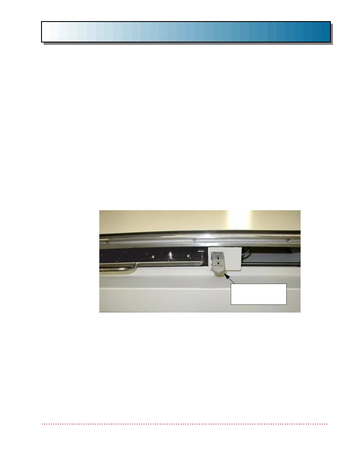
IMAGE RECEPTOR CABINET LOCK
The Image Receptor Cabinet rides on four linear ball-bearings mounted to adjust-
able brackets attached to either side of the cabinet (see Figure 7). These bear-
ings travel on the hardened and polished steel shafts of the Receptor Cabinet
Carriage. An electromagnet on the underside of the housing "locks" the cabinet
into place until the LOCK RELEASE switch is depressed, thereby releasing the
magnet’s hold and allowing free movement of the cabinet.
CASSETTE TRAY OPERATION
The radiographic table is equipped with either a Midwest or Poersch cassette tray,
depending on the system ordered. The following paragraphs describe the operat-
ing instructions for each. Additional information is contained in the cassette tray
manufacturer’s documentation, which is provided with the table.
LOCK RELEASE
SWITCH
Figure 7. Image Receptor Cabinet LOCK RELEASE Switch