GSM /GPRS Modem
GSM /GPRS Modem GSM /GPRS Modem
GSM /GPRS Modem
GSM
GSM GSM
GSM-
--
-Q2403
Q2403Q2403
Q2403
DS GSM-Q2403-1 ©2011 www.quasaruk.co.uk . Page 3
Interface description
Interface descriptionInterface description
Interface description
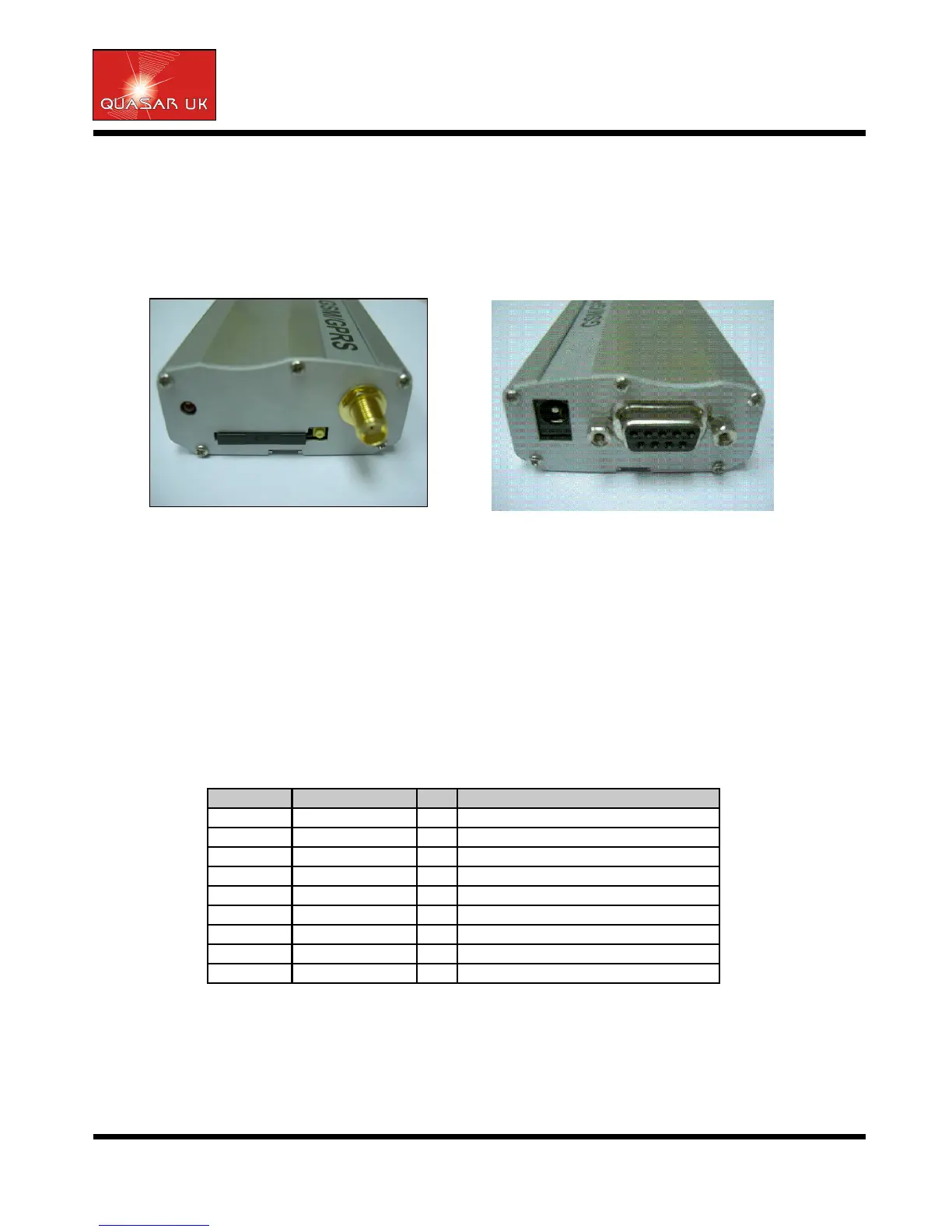
The GSM Terminal provides the following connectors for power supply, interfacing and antenna:
• 2.1mm DC power connector (centre/inner pin is positive)
• 9-pin (female) D-SUB plug for RS-232 serial interface
• SMA connector for antenna (radio interface)
• SIM card holder
Power Supply
Power SupplyPower Supply
Power Supply
The power supply of the GSM Terminal should be a single voltage source of Vin=6-36V providing a peak
current of up to 500mA during transmission.
The terminal can be turned on by connecting power. The terminal power supply circuit automatically gen-
erates a low pulse signal not less than 100ms in order to wake up the GSM engine.
Each time the terminal is shut down, data will be written from the volatile memory to flash memory. The
guaranteed maximum number of write cycles is limited to 100,000.
RS232 Interface
RS232 InterfaceRS232 Interface
RS232 Interface
Via RS-232 interface, the host controller controls the TMAS GSM/GPRS Terminal and transports data.
The table below shows the pin assignment of RS-232 (D-SUB 9-pin female).
The GSM/GPRS Terminal is designed for use as DCE. Based on the conventions for DCE-DTE connection,
it communicates with the user application (DTE) using the following signals:
Pin TxD @ application sends data to TxD of GSM/GPRS Terminal
Pin RxD @ application receives data from RxD of GSM/GPRS Terminal
Pin no.
Pin no.Pin no.
Pin no.
Signal name
Signal nameSignal name
Signal name
I/O
I/OI/O
I/O
Function
FunctionFunction
Function
1
/DCD
O
Data Carrier Detected
2
/RXD
O
Receive Data
3
/TXD
I
Transmit Data
4
/DTR
I
Data Terminal Ready
5
GND
-
Ground
6
/DSR
O
Data Set Ready
7
/RTS
I
Request To Send
8
/CTS
O
Clear To Send
9
/RI
O
Ring Indication
 Loading...