2000 – Input I2 influences on the cooling valve according to status
of condense sensor, In this case function of setpoint selection with
I2 is disabled
Parameter no. 40–Power reporting in Watts on power change for Q1
Set value means percentage, set value from 0 - 100=0% - 100%.
Available configuration parameters (data type is 1 Byte DEC):
default value 3
0 – Reporting Disabled
1–100 = 1%-100% Reporting enabled. Power report is send (push)
only when actual power in Watts in real time changes for more than set
percentage comparing to previous actual power in Watts, step is 1%.
NOTE: If power changed is less than 1W, the report is not send (pushed),
independent of percentage set.
Parameter no. 41–Power reporting in Watts on power change for Q2
Set value means percentage, set value from 0 – 100 = 0% - 100%.
Available configuration parameters (data type is 1 Byte DEC):
default value 3
0 – Reporting Disabled
1 – 100 = 1% - 100% Reporting enabled. Power report is send
(push) only when actual power in Watts in real time changes for
more than set percentage comparing to previous actual power in
Watts, step is 1%.
NOTE: if power changed is less than 1W, the report is not send (pushed),
independent of percentage set.
Parameter no. 42 – Power reporting in Watts by time interval for Q1
Set value means time interval (0 – 65535) in seconds, when power
report is send. Available config. parameters (data type is 2 Byte DEC):
default value 300 (power report in Watts is send each 300s)
0 – Reporting Disabled
1 – 65535 = 1second – 65535 seconds. Reporting enabled. Power
report is send with time interval set by entered value.
Parameter no. 43 – Power reporting in Watts by time interval for Q2
Set value means time interval (0 – 65535) in seconds, when power
report is send. Available config. parameters (data type is 2 Byte DEC):
default value 300 (power report in Watts is send each 300s)
0 – Reporting Disabled
1 – 65535 = 1 second – 65535 seconds. Reporting enabled, Power
report is send with time interval set by entered value.
Parameter no. 50 – Hysteresis Heating On
This parameter defines temperature difference between measured
temperature and set-point temperature to turn heating on. Parameter
can be set from 0 to 255 where 0 to 127 means from 0.0 °C to 12.7 °C
and from 128 to 255 means from - 0.1 °C to -12.7 °C.
Available configuration parameters (data type is 1 Byte DEC):
default value 137 (-1.0 °C)
Parameter no. 51 - Hysteresis Heating Off
This parameter defines temperature difference between measured
temperature and set-point temperature to turn heating off. Parameter
can be set from 0 to 255 where 0 to 127 means from 0.0 °C to 12.7°C
and from 128 to 255 means from - 0.1 °C to -12.7 °C.
Available configuration parameters (data type is 1 Byte DEC):
default value 132 (-0.5 °C)
Parameter no. 52 – Hysteresis Cooling On
This parameter defines temperature difference between measured
temperature and set-point temperature to turn cooling on. Parameter
can be set from 0 to 255 where 0 to 127 means from 0.0 °C to 12.7 °C
and from 128 to 255 means from - 0.1 °C to -12.7 °C.
Available configuration parameters (data type is 1 Byte DEC):
default value 10 (1.0 °C)
Parameter no. 53 – Hysteresis Cooling Off
This parameter defines temperature difference between measured
temperature and set-point temperature to turn cooling off. Parameter
can be set from 0 to 255 where 0 to 127 means from 0.0 °C to 12.7 °C
and from 128 to 255 means from - 0.1 °C to -12.7 °C.
Available configuration parameters (data type is 1 Byte DEC):
default value 5 (+0.5 °C)
Parameter no. 54 – Antifreeze
Set value means at which temperature the heating will be turned on (to
prevent freezing) even if the thermostat was manually set to off.
Parameter can be set from 0 to 255 where 0 to 127 means from 0.0 °C
to 12.7 °C and from 128 to 254 means from - 0.1 °C to -12.6 °C.
Available configuration parameters (data type is 1 Byte DEC):
default value 50 (5,0 °C)
255 – antifreeze functionality disabled
Parameter no. 60 – Too low temperature limit
Available configuration parameters (data type is 2 Byte DEC):
Default value 50 (Too low temperature limit is 5.0°C)
1 - 1000 = 0.1°C – 100.0°C, step is 0.1°C. Too low temperature limit
is set by entered value. In case measured temperature is below set
value, module send BasicSet value. Look chapter associations.
Parameter no. 61 – Too high temperature limit
Available configuration parameters (data type is 2 Byte DEC):
Default value 700 (too high temperature limit is 70.0°C)
1 - 1000 = 0.1°C – 100.0°C, step is 0.1°C. Too high temperature limit
is set by entered value. In case measured temperature is higher
than set value, module send BasicSet value. Look chapter
associations.
Parameter no. 64 – Q1 Switch selection
Set value means the type of the heating device that is connected to the
relay output. The heating device type can be normally open (NO) or
normally close (NC).
Available configuration parameters (data type is 1 Byte DEC):
default value 0
0 - When system is turned off the output is 0VAC (NC).
1 - When system is turned off the output is 230VAC (NO)
Parameter no. 65 – Q2 Switch selection
Set value means the type of the cooling device that is connected to the
relay output. The cooling device type can be normally open (NO) or
normally close (NC).
Available configuration parameters (data type is 1 Byte DEC):
default value 0
0 - When system is turned off the output is 0VAC (NC).
1 - When system is turned off the output is 230VAC (NO).
Functionality
Thermostat has 2 working mode, Off or Auto. Selection between Off and
Auto is possible to select with I1 push button or from gateway. When the
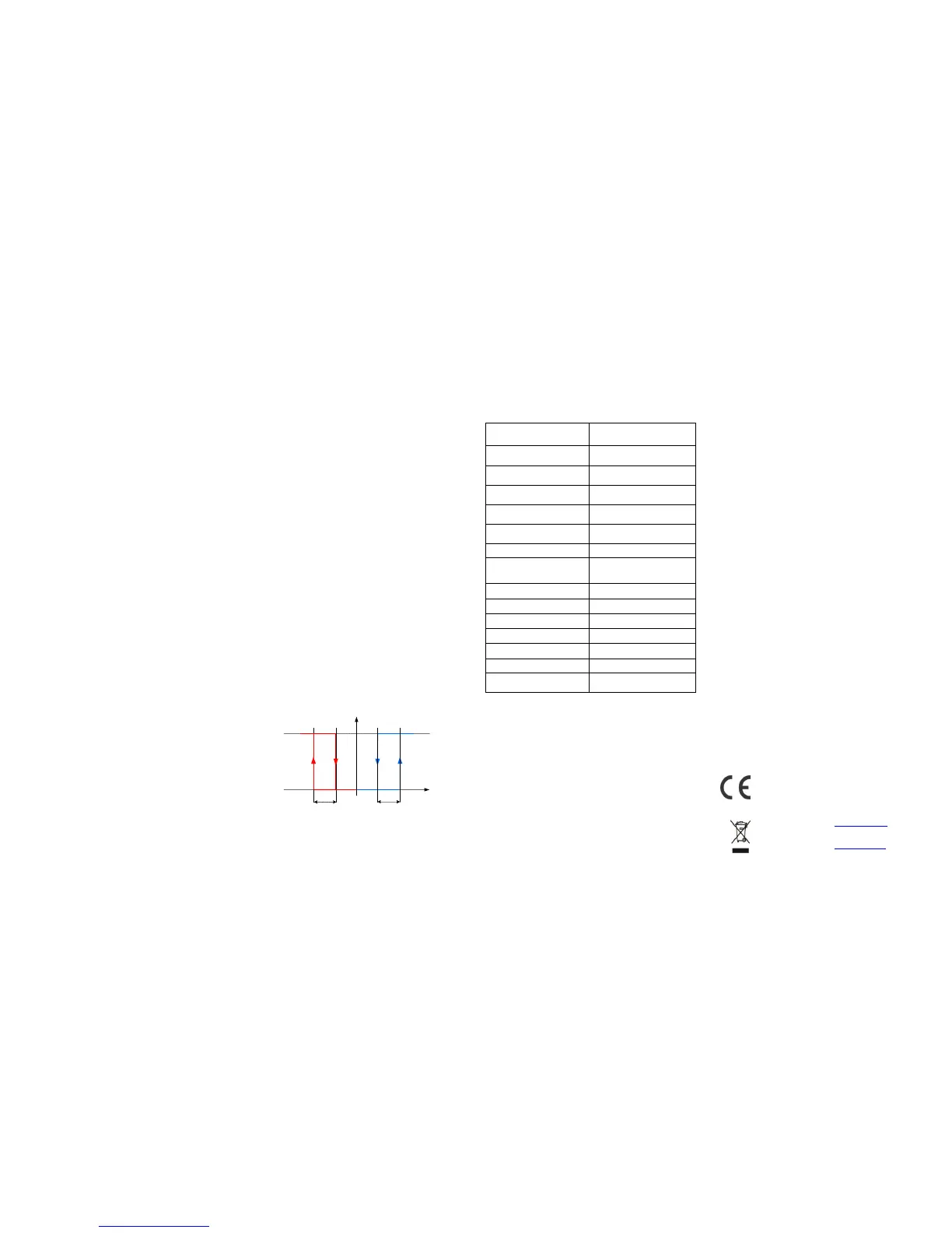
thermostat is turned On, it automatically regulates temperature
according to picture below:
When the temperature is decreasing and reaches point ‘Heating On’
(defined by parameter 50), heating is turned on and remains active until
the temperature in the room is not increased to reach ‘Heating Off’
(defined by parameter 51). At this point heating and cooling valve are
turned off – deadband zone. If the temperature rises over ‘Cooling On’
(defined by parameter 52) point the cooling valve will switch on. The
consequence will be temperature dropping, and when temperature
drops below ‘Cooling Off’ (defined by parameter 53) cooling valve will
switch off.
When the thermostat is turned off, then it is working in antifreeze regime.
The antifreeze regime turns on heating when the temperature is lower or
equal to the temperature set by parameter 54 (Default 5.0C).
Energy saving mode:
If parameter 11 is set to value 2 and if the state of the input I1 is active
(window opened active) both outputs (Q1 and Q2) are turned off.
Condensation:
If parameter 12 is set to value 2000 and if the state of the input I2 is
active (condensation sensor active) Q2 output (cooling) is turned off.
Temperature limits
Temperature too low is send when the actual temperature is equal
or smaller to the value set by parameter 60 (Check Associated
Groups)
Temperature too high is send when the actual temperature is equal
or higher to the value set by parameter 61. (Check Associated
Groups)
Technical Specifications
* In case of load other than resistive, pay attention to the value of cos φ
and if necessary apply load lower than the rated load. Max current for
cos φ=0,4 is 2A at 250VAC, 3A at 24VDC.
Z-Wave Device Class:
BASIC_TYPE_ROUTING_SLAVE
GENERIC_TYPE_THERMOSTAT
SPECIFIC_TYPE_SETPOINT_THERMOSTAT
Z-Wave Supported CommandClasses:
COMMAND_CLASS_THERMOSTAT_SETPOINT v2
COMMAND_CLASS_VERSION v1
COMMAND_CLASS_MANUFACTURER_SPECIFIC v1
COMMAND_CLASS_MULTI_CMD v1
COMMAND_CLASS_SENSOR_MULTILEVEL v3
COMMAND_CLASS_ASSOCIATION v1
COMMAND_CLASS_CONFIGURATION v1
COMMAND_CLASS_POWERLEVEL v1
COMMAND_CLASS_METER v3
COMMAND_CLASS_THERMOSTAT_MODE v2
COMMAND_CLASS_MARK
COMMAND_CLASS_BASIC v1
COMMAND_CLASS_NO_OPERATION
Endpoint 2 (I1):
Device Class:
GENERIC_TYPE_SWITCH_BINARY
SPECIFIC_TYPE_POWER_SWITCH_BINARY
Command Classes:
COMMAND_CLASS_SWITCH_BINARY
COMMAND_CLASS_METER_V3
Endpoint 3 (I2):
Device Class:
GENERIC_TYPE_SWITCH_BINARY
SPECIFIC_TYPE_POWER_SWITCH_BINARY
Command Classes:
COMMAND_CLASS_SWITCH_BINARY
COMMAND_CLASS_METER_V3
COMMAND_CLASS_BASIC
The basic command class supports the functions BASIC SET and
BASIC GET. Through the function basic SET is possible to set the mode
of the module. Basic SET can send the values 0xff which means Auto
and 0x00 which means Off. Through the function basic GET is possible
to read the mode of the module. The module returns 0xff which means
Auto or 0x00 which means Off.
COMMAND_CLASS_SENSOR_MULTILEVEL
The Flush on/off thermostat supports reading of actual temperature
which is 2 bytes long, scale is °C and its precision is 1(it means 0,1°C).
COMMAND_CLASS_THERMOSTAT_MODE
The Flush heat & cool thermostat supports the following modes:
Mode Off
Mode Auto
COMMAND_CLASS_THERMOSTAT_SETPOINT
The Flush on/off thermostat supports temperature set point, which is
2 bytes long, scale is °C and its precision is 1(it means 0,1°C).
This product can be included and operated in any Z-Wave network with
other Z-Wave certified devices from any other manufacturers. All
constantly powered nodes in the same network will act as repeaters
regardless of the vendor in order to increase reliability of the network.
Important disclaimer
Z-Wave wireless communication is inherently not always 100% reliable,
and as such, this product should not be used in situations in which life
and/or valuables are solely dependent on its function.
Warning!
Do not dispose of electrical appliances as unsorted municipal waste, use
separate collection facilities.
Contact your local government for information regarding the collection
systems available. If electrical appliances are disposed of in landfills or
dumps, hazardous substances can leak into the groundwater and get
into the food chain, damaging your health and well-being. When
replacing old appliances with new once, the retailer is legally obligated to
take back your old appliance for disposal at least for free of charge.
This user manual is subject to change and improvement without notice.
Qubino
Goap d.o.o. Nova Gorica
Ulica Klementa Juga 007
5250 Solkan
Slovenia
E-mail: info@qubino.com
Tel: +386 5 335 95 00
Web: www.qubino.com
Date: 13.04.2015
Document: Qubino_Flush heat & cool
thermostat user manual_V1.2_eng
 Loading...