TITLE
PROJECT
Yeoman CHEN
CHECKED BY
Eden LIU
DRAWN BY
OF
A
6
5
4
32
1
SHEET
A
B
C
D
123456
D
C
B
Quectel Wireless Solutions
SIZE
VER
108
C
DATE
2016/11/11
Reference DesignEC25
A2
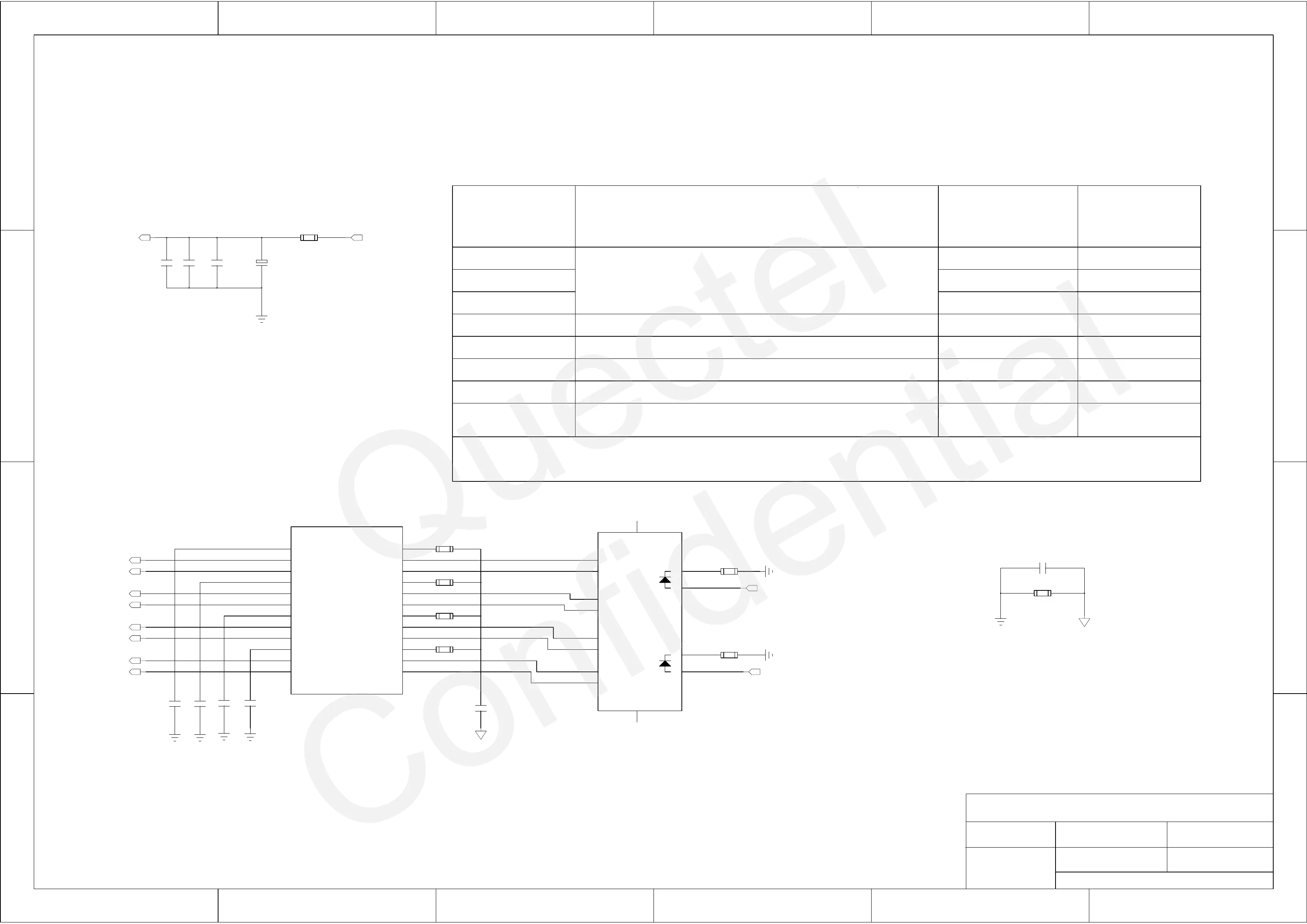
SGMII Design (Part 2)
Description
PHY_AD[2:0] set the lower three bits of the physical address.
The upper two bits of the physical address are set to 00.
Default internal
1
PHY core
PHY_AD2
PHY_AD1
PHY_AD0
MODE 3
MODE 2
MODE 1
MODE 0
EXT_INT_SEL
1. Differential pair P/N skew must be less than 20 mils, and the maximum trace length must be less than 10 inches.
2. Using the 100 ohm ± 10% differential impedance with 50 ohm ± 10% single-ended impedance.
3. To minimize crosstalk, the distance between separate adjacent pairs that are on the same layer must be equal to or larger than 40 mils.
Notes:
4. Copper filling around transformers is prohibited for better ESD protection performance.
5. For better EMI suppression performance, do not route in top layer.
weak pull-up/downconfiguration signal
0
0
0
0
0
0
0
0
0
0
0
0
1
1
0
weak pull-up/down
Application external
Mode select bit 3
Mode select bit 2
Mode select bit 1
Mode select bit 0
An external 10K pull-down resistor is required.
0=Pull-down, 1=Pull-up.
R801
0R
+
C804
100uF
C802
33pF
C801
10pF
C803
100nF
1
TCT1
2
TD1+
3
TD1-
4
TCT2
5
TD2+
6
TD2-
7
TCT3
8
TD3+
9
TD3-
10
TCT4
11
TD4+
12
TD4-
13
MX4-
14
MX4+
15
MCT4
16
MX3-
17
MX3+
18
MCT3
19
MX2-
20
MX2+
21
MCT2
22
MX1-
23
MX1+
24
MCT1
U801
FC3004
C806
0.1uF
C807
0.1uF
C808
0.1uF
C809
0.1uF
1
TA+
14
H2
13
H1
3
TB+
5
TC-
7
TD+
2
TA-
4
TC+
6
TB-
8
TD-
9
G-
10
G+
11
Y-
12
Y+
J801
FC601-56-LED
R802
75R 1%
R804
75R 1%
R805
75R 1%
R807
75R 1%
C805
1000pF/2KV_NM
C810
1000pF/2KV
R803
510R
R808
510R
R806
0R
[7]
VDD33_SGMII
[3]
VDD3V3
[7]
LED_ACT
[7]
LED_1000
[7]
TRXP0
[7]
TRXN0
[7]
TRXP1
[7]
TRXN1
[7]
TRXP2
[7]
TRXN2
[7]
TRXP3
[7]
TRXN3