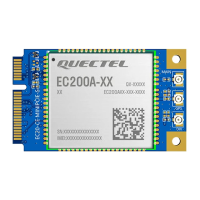
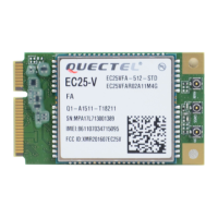
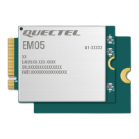
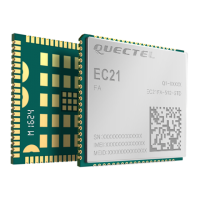
Do you have a question about the Quectel EC200U Series and is the answer not in the manual?
Defines special symbols and notations used throughout the document for clarity.
Overview of EC200U series module, its communication capabilities, and supported networks.
Lists and details the primary features, hardware capabilities, and specifications of the module.
Presents a block diagram showing the internal architecture and major functional components.
Displays the physical pinout of the EC200U series module, indicating pin locations and numbers.
Provides detailed information on each pin's function, I/O type, and electrical characteristics.
Covers power supply requirements, pins, voltage stability, and reference design for the module.
Explains procedures and circuits for module power control and system reset.
Details (U)SIM card interface pin definitions, voltage support, and hot-plug functionality.
Describes the USB 2.0 interface, data transfer rates, pinout, and application circuits.
Explains the main, debug, and auxiliary UART interfaces, including baud rates and flow control.
Defines pins for main, Wi-Fi, and Bluetooth antennas and their operating frequencies.
Provides guidelines for PCB layout of RF traces to ensure optimal characteristic impedance.
Outlines antenna requirements and recommends suitable RF connectors for installation.
Lists the critical voltage and current limits for power supply and signal pins.
Specifies recommended voltage range, voltage drop, and peak current for the power supply.
Details current draw of the module in various states like sleep, idle, and data transfer.
Presents specifications for the radio frequency output power across different bands.
Shows the conducted radio frequency receiving sensitivity for various network bands.
Provides the physical size, outline, and dimensional tolerances of the module.
Shows the recommended land pattern for surface mounting the module on a PCB.
Specifies recommended temperature and humidity for module storage to ensure quality.
Guides on soldering processes, thermal profiles, and handling precautions.
| Module Type | LTE Cat 1 Module |
|---|---|
| Category | Control Unit |
| LTE Category | Cat 1 |
| Form Factor | LCC |
| GSM/GPRS/EDGE Bands | 850/900/1800/1900 MHz |
| Operating Temperature | -40°C to +85°C |
| Storage Temperature | -45°C to +90°C |
| SIM Interface | 1.8V/3.0V |
| GNSS | GPS/GLONASS/BeiDou/Galileo/QZSS |
| LTE Bands | B1/B3/B5/B8/B20/B28 |
| UMTS/HSPA(+) Bands | B1/B5/B8 |
| Data Rate LTE | 10Mbps (DL)/5Mbps (UL) |
| Data Rate HSPA+ | 5.76Mbps (UL) |
| Data Rate UMTS | 384kbps (DL)/384kbps (UL) |
| Data Rate EDGE | 236.8 Kbps |
| Data Rate GPRS | 85.6kbps (DL)/85.6kbps (UL) |
| Power Supply | 3.3V |
| Power Consumption (Connected Mode) | ≤ 100 mA |
| Interface | USB, UART, I2C, GPIO |
| Protocols | TCP/UDP/PPP/FTP/HTTP/MQTT/SSL |
| Firmware Update | USB/FOTA |
| Certifications | CE, FCC |


