Do you have a question about the Quectel EC200T Series and is the answer not in the manual?
Safety precautions for operation, usage, service, and repair of the EC200T series module.
Overview of the EC200T series LTE module, its capabilities, and variants.
Detailed features of the EC200T series module, including power supply and transmitting power.
Block diagram of the EC200T series module illustrating major functional parts.
Information on Quectel's evaluation board and peripherals for EC200T series development.
Description of the EC200T series module's 80 LCC and 64 LGA pins and interfaces.
Top view pin assignment diagram for the EC200T series module.
Detailed definitions and characteristics of the EC200T series module's pins.
Overview of EC200T series module operating modes like Normal, Idle, Sleep, and Power Down.
Methods for reducing EC200T series module current consumption, focusing on Sleep Mode.
Details on EC200T series module power supply pins and voltage drop considerations.
Procedures and reference circuits for turning on, turning off, and resetting the module.
Specifications and reference designs for the (U)SIM interface of the EC200T series module.
Details on the EC200T series module's USB 2.0 interface and application reference circuit.
Features and pin definitions for the main and debug UART interfaces of the EC200T series module.
PCM and I2C interfaces for audio design, including timing and reference circuits.
Definition and reference design for the SD card interface of the EC200T series module.
Information on the SDIO 3.0 interface for WLAN on the EC200T series module.
Description of the two analog-to-digital converter (ADC) interfaces on the EC200T series module.
Pins for driving network status indication LEDs, including pin definition and logic level changes.
The STATUS pin as an open drain output for module operation status indication.
Configuration and default behavior of the MAIN_RI pin for Unsolicited Result Codes (URCs).
Using the FORCE_USB_BOOT pin to enter emergency download mode for firmware upgrade.
Pin definition and operating frequencies for main and Rx-diversity antenna interfaces.
Requirements and recommendations for installing antennas, including RF layout.
Absolute maximum ratings for power supply and voltage on digital and analog pins.
Module power supply ratings, including voltage, drop, and peak current.
Operating and storage temperature ranges for the EC200T series module.
Detailed current consumption data for EC200T-CN, -EU, and -AU* modules in various states.
RF output power specifications for EC200T series modules across different frequency bands.
Conducted RF receiving sensitivity for EC200T-CN, -EU, and -AU* modules.
Electrostatic discharge (ESD) characteristics and handling precautions for the module.
Physical dimensions of the EC200T series module, including top, side, and bottom views.
Recommended PCB footprint for the EC200T series module, including keepout area.
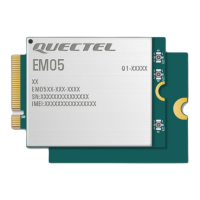
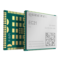
Renderings of the EC200T series module's top and bottom views.
Recommended storage conditions, shelf life, and handling precautions for the module.
Guidelines for manufacturing and soldering the EC200T series module, including reflow thermal profile.
Details on the packaging of EC200T series modules in tape and reel carriers.
| Category | Control Unit |
|---|---|
| Form Factor | LCC |
| Operating Temperature | -40°C to +85°C |
| Storage Temperature | -45°C to +90°C |
| Max Data Rate (DL) | 10 Mbps |
| Max Data Rate (UL) | 5 Mbps |
| GNSS | GPS/GLONASS/BeiDou/Galileo/QZSS |
| Dimensions | 32.0mm × 29.0mm × 2.4mm |
| UMTS Frequency Bands | B1/B5/B8 |
| GSM Frequency Bands | 900/1800MHz |
| Interface | USB 2.0, UART |
| SIM Interface | 1.8V/3.0V |
| Protocols | TCP/UDP/HTTP/MQTT |
| Approvals | CE, GCF |
| Certifications | RoHS, REACH |
| LTE Frequency Bands | B1/B3/B5/B8/B20/B28 |


