LTE Standard Module Series
EC200U_Series_Hardware_Design 61 / 94
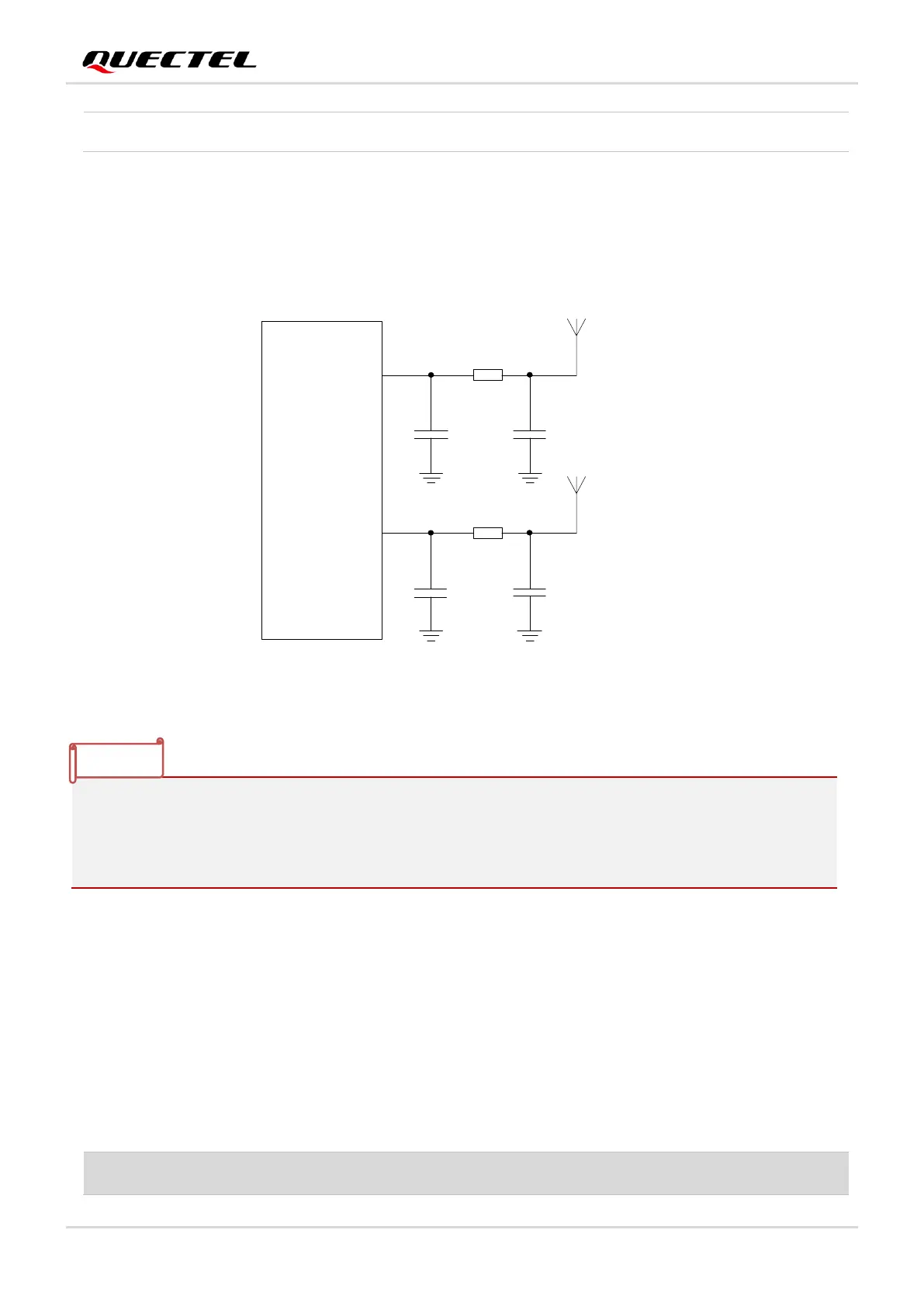
4.1.3. Reference Design of RF Antenna Interfaces
A reference design of ANT_MAIN and ANT_BT/WIFI_SCAN is shown as below. A π-type matching circuit
should be reserved for better RF performance. The capacitors are not mounted by default.
ANT_MAIN
R1 0R
C1
Module
Main
antenna
NM
C2
NM
R2 0R
C3
Wi-Fi Scan/
Bluetooth
antenna
NM
C4
NM
ANT_BT/WIFI
_SCAN
Figure 29: Reference Circuit of RF Antenna Interfaces
4.2. GNSS Antenna Interface
The following tables list the pin definition and frequency characteristics of the GNSS antenna interface
respectively.
Table 37: Pin Definition of GNSS Antenna Interface
1. In order to improve the receiving sensitivity, it is necessary to ensure the proper distance between
the main antenna and Wi-Fi Scan/Bluetooth receiving antenna.
2. Place the π-type matching components (R1 & C1 & C2 and R2 & C3 & C4) as close to the antenna
as possible.

 Loading...


