EN
BTR185 INSTALLATION AND USE MANUAL - REV009A
33
BTR1854 - Installation
Fig. 14
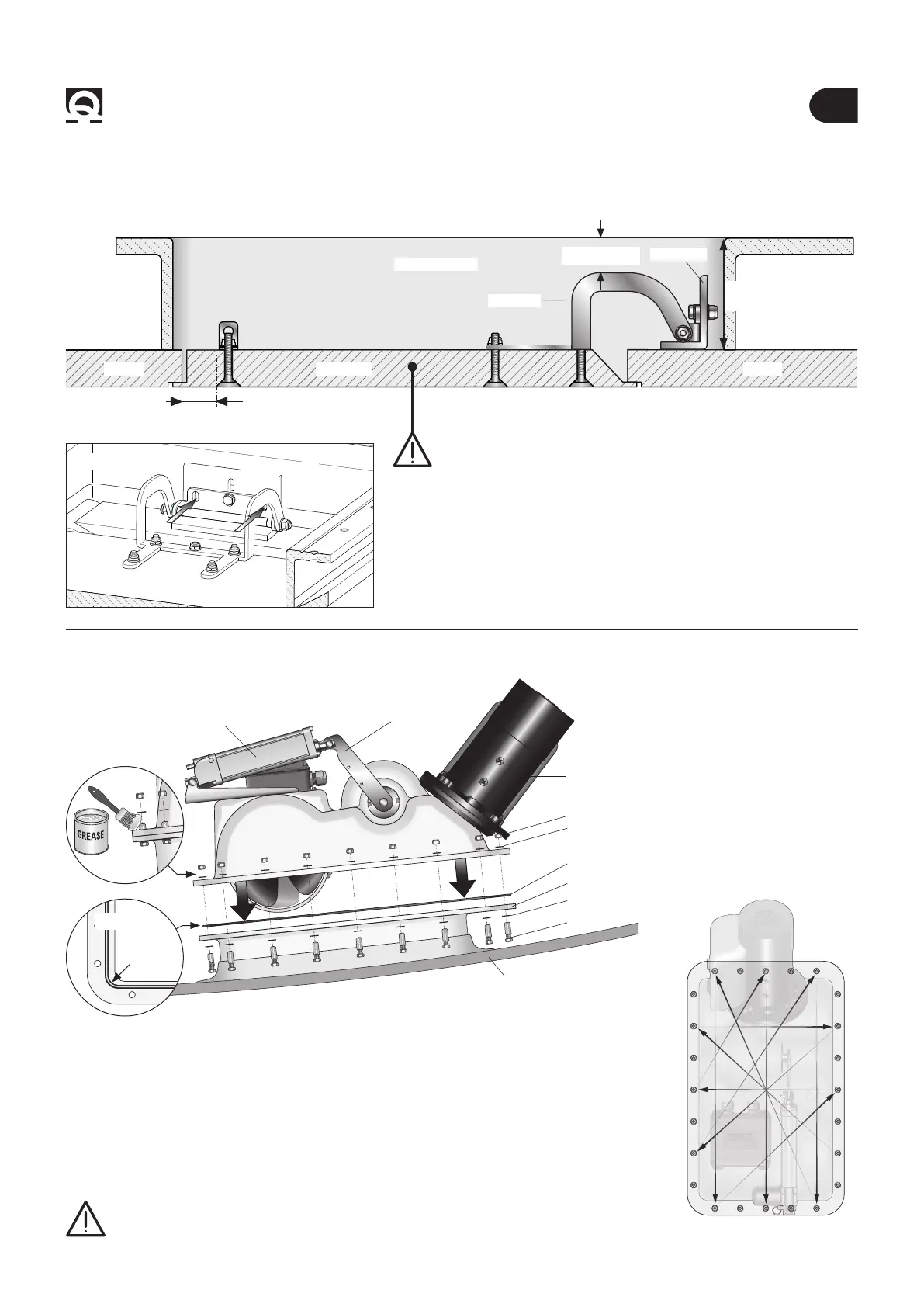
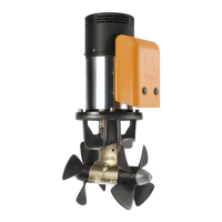
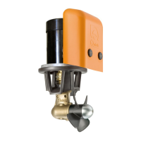
4.3 - Thruster’s installation
Fig. 12
15 mm
LID
Min. 80 mm
COUNTER FLANGE
HINGE
ANGLE BAR
HULLHULL
• Drill the angle bar and fasten securely with the other two M8 screws
(g. 13).
N 2 SCREWS M8
Fig. 13
WARNING: in order to allow a stable xing of hinge and bracket,
the lid must present neither empty areas nor non-structural llings
inside (g. 12).
Min. 5 mm
• Remove the adhesive backings, previously applied, from the counter ange.
• Make sure the area where the gasket will be positioned is clean and has not suffered
any damage during installation.
• Position the o-ring on the counter ange (part. 14A), assemble the thruster (g.14),
spread marine grease on the thread of the bolts (g.14B) and fasten securely with sup-
plied screws.
O-RING
BOLT
WASHER
MOTOR
WASHER
NUT
COUNTER FLANGE
HULL
THRUSTER
F
The bolts and screws of the counter ange must be tightened to 25Nm, tightening
little by little in a crossed sequence, following a scheme such as in the example in
gure 14C.
WARNING: about one week after installation, you should check that all screws are
properly tightened in order to compensate for any potential o-ring settling.
ACTUATOR
ACTUATOR
HANDLE
Fig. 14C
1
2 3
10 9
4
8
7
12
11
6
5
Part. 14B
O-RING
Part. 14A