24
EN
RETRACTABLE THRUSTER BTR185 - IT EN - REV008B
INSTALLATION
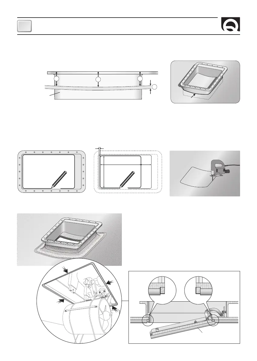
Counter flange’s installation
Directly access inside the hull, where the thruster will be installed.
Fig. 1A
• Mark with a felt-tip pen the internal
perimeter of the counter flange (fig. 2).
The thruster position must enable easy maintenance operations.
F
Fig. 2 Fig. 3
• In the two positions (X) of the long sides of the counter flange, the height must be 80/100 mm less the hull’s thickness (SP).
Adapt the shape of the central part of the counter flange (Y) to the hull’s curve (fig. 1A).
• Shape the short sides of the counter flange like the hull’s curve, in the position where it’s meant to be fixed (fig. 1B).
• Lay the properly-cut counter flange and check that the four sides fit the hull, or adjust them until they do fit in the position where
the counter flange is meant to be fixed.
• Cut the hull along the cutting area pre-
viously marked (fig. 4).
• Align the counter flange to the hull’s opening and check that
the two heights (X) are correct. Resinate the counter flange, or
solder it in case of aluminium or steel, according to the techni-
ques the most suitable to the hull’s material (fig. 5).
Fig. 4
Fig. 5
• Make a solid coaming for the closing lid on the whole perimeter
of the hull’s opening (fig. 6).
•
Remove the counter flange and mark the
cutting area: 350 x 280 mm (fig. 3).
LID
HULL
Fig. 6
COUNTER FLANGE
SP
X
X
Y
HULL
COUNTER FLANGE
(X = 80/100 mm
-
SP)
Fig. 1B
350 mm 95 mm
mm
280 mm