25
INSTALLATION
EN
RETRACTABLE THRUSTER BTR185 - IT EN - REV008B
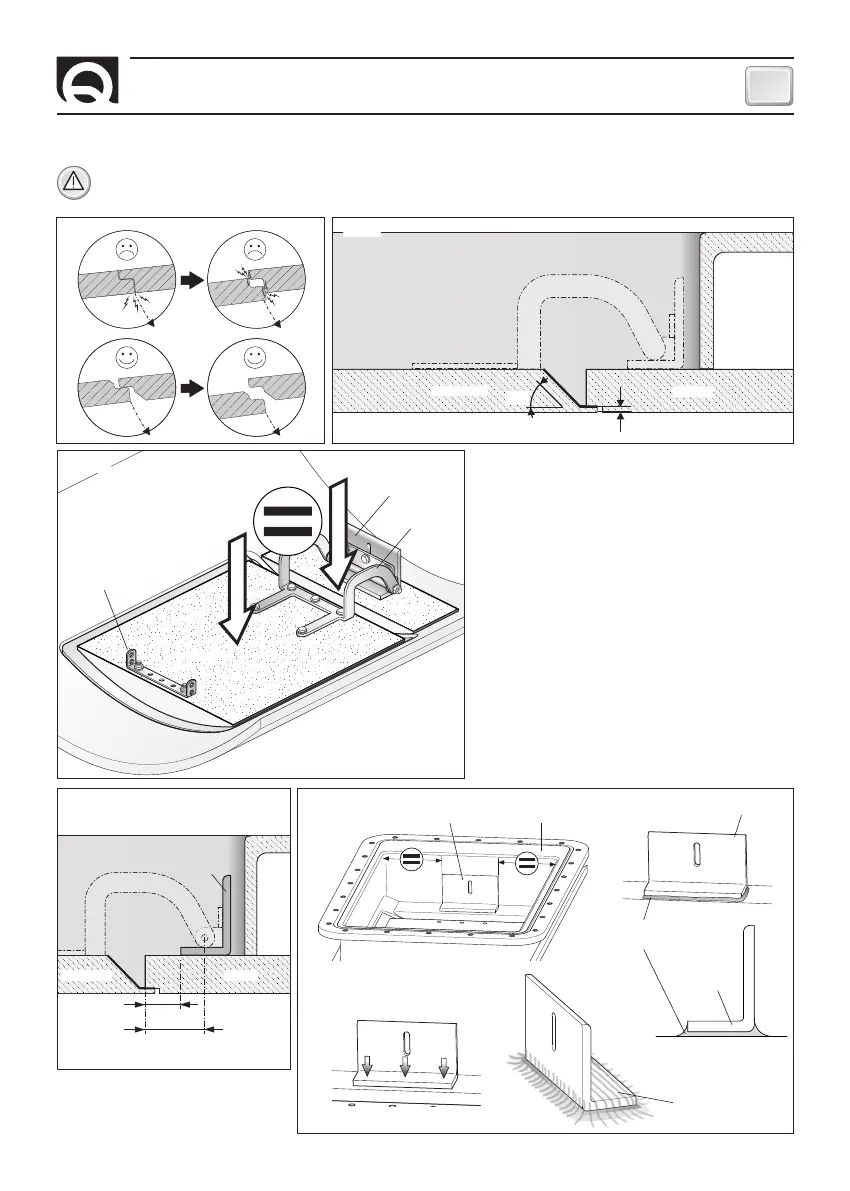
Fig. 7
WARNING: pay particular attention to avoid interferences between the lid and the hull opening. Too precise contacts will
cause damages to the entire moving system.
• Make the closing lid by keeping on all sides a space
varying from 3 to 5 mm (fig. 7), paying special atten-
tion to the hinge’s side, ensuring that the internal wal-
ls are inclined by 45° so that they don’t hinder the
hull’s opening (fig. 8).
• To obtain the correct opening of the hinge, the surfa-
ces of hull and lid must be on the same level (fig. 9).
45°
5 mm
Closing lid’s preparation and installation
LID HULL
COUNTER FLANGE
LID BRACKET
Fig. 8
Fig. 10A
LID HULL
COUNTER FLANGE
LID BRACKET
HINGE
26 mm
45 mm
Fig. 10B
A
B1
B2
C1
COLLA
STRUTTURALE
GRP LAYERS
N 3 SCREWS M8
Fig. 9
LID
LID’S
BRACKET
HULL
HINGE
LID BRACKET COUNTER FLANGE
C2
LID BRACKET
LID BRACKET
STRUCTURAL
GLUE
• Position the angle bar correctly on the hull
(fig. 10A+10B - part. A).
Fasten the angle bar with structural adhesive
(fig. 10B - part. B1-B2).
Decide whether to fasten the lid bracket to the hull
with 3 M8 screws or with resin (fig. 10B - part. C1-C2).