26
EN
RETRACTABLE THRUSTER BTR185 - IT EN - REV008B
Conversion from decimal to fractional inches
3 mm = 1/8” in 26 mm = 1” 1/32 in
5 mm = 3/16” in 35 mm = 1” 3/8 in
8 mm = 5/16” in 45 mm = 1” 49/64 in
8,5 mm = 21/64” in 80 mm = 3” 5/32 in
10 mm = 25/64” in 95 mm = 3” 3/4 in
15 mm = 19/32” in 100 mm = 3” 15/16 in
20 mm = 25/32” in 280 mm = 11” 1/32 in
350 mm = 13” 25/32 in
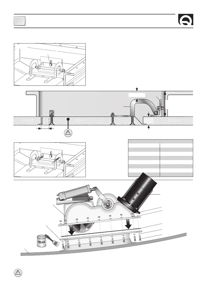
INSTALLATION
Fig. 14
• Assemble the thruster to the counter flange, which is now integral with the hull, by means of the bolts and screws provided
(spread some marine grease on the bolts’ thread), by verifying the correct positioning of the gasket on the counter flange (fig.14).
WARNING: about one week after installation, you should check that all screws are properly tightened in order to compen
-
sate for any potential O-ring settling.
Thruster’s installation
Fig. 12
15 mm
LID
Max
35 mm
COUNTER FLANGE
HINGE
LID BRACKET
HULLHULL
• Temporarily fasten the hinge bracket in its housing.
• Screw the hinge onto the lid bracket with the central screw only (fig. 11).
• Position the hinge and hinge bracket correctly in the correct positions.
Mark all the fastening points (fig. 12), remove the hinge and hinge bracket
and drill using the Ø 8.5 mm bit.
Fasten the hinge and hinge bracket in the positions marked with stainless
steel hardware suitable for the application.
Adjust the central screw of the hinge (fig. 11) and position it correctly so
that the hatch opens without any hindrance.
CENTRAL SCREW
Fig. 11
Closing lid’s preparation and installation
• Drill the angle bar and
fasten securely with
the other two M8
screws (fig. 13).
N. 2 SCREWS M8
Fig. 13
O-RING
BOLT
WASHER
MOTOR
WASHER
NUT
COUNTER FLANGE
HULL
THRUSTER
Min.
80 mm
WARNING: in order to allow a stable fixing of hinge and bracket, the lid must present
neither empty areas nor non-structural fillings inside (fig. 12).
Min. 5 mm