931134 Rev. A
IX. Set-up & Adjustment
33
IX. Set-up & Adjustment
931134 Rev. A
32
J. ANTI-TIP TUBES- BACK
Anti-tip tubes are recommended for all wheelchairs.
NOTE– Use a torque setting of 350 in.-lbs. When set-
ting-up anti-tip tubes.
1. Inserting Anti-Tip Tubes Into Receivers
a. Press the rear anti-tip release pin (A) on the
anti-tip tube so that both release pins are
drawn inside.
b. Insert the anti-tip tube into the receiver (B).
c. Turn the anti-tip tube down until release pin
protrudes through the receiver mounting hole.
d. Insert second anti-tip tube the same way.
2. Turning Anti-Tip Tubes Up
Turn anti-tip tubes up when being pushed by atten-
dant, overcoming obstacles or climbing curbs.
a. Press the rear anti-tip tube release pin (A).
b. Hold pin in and turn anti-tip tube up (C).
c. Release pin.
d. Repeat with second anti-tip tube.
e. Remember to return anti-tip tubes to down
position after completing maneuver.
3. Adjusting Anti-Tip Tube Wheel
The anti-tip tube wheels may have to be raised or low-
ered to achieve proper ground clearance (1-1/2" to 2").
a. Press the anti-tip wheel release pin (D) so that
the release pin is drawn inside.
b. Raise or lower to one of the three or four pre-
drilled holes.
c. Release pin (D).
d. Adjust the second anti-tip tube wheel the same
way. Both wheels should be at exactly the same
height.
4. Height adjustment of the receivers
a. Remove anti-tip tubes (E) from anti-tip
receivers (B).
b. Remove bolts (F) from anti-tip tube receiver.
c. Reposition bracket to desired height. The receiver
can be positioned up or down as needed.
d. Reinsert bolts (F) and tighten.
e. Repeat with second anti-tip tube receiver. Both
brackets should be at exactly the same height.
f. Replace anti-tip tubes.
A
B
C
D
B
E
F
5. Adjusting Armrest Receiver Fit
To tighten or loosen the fit of the outer armpost in the
receiver:
a. Loosen all four bolts (9) on the sides of the
receiver (2).
b. With the armrest in the receiver, squeeze the
receiver to achieve the desired fit.
c. Tighten all four bolts (9).
6. Adjusting Inner Armpost Fit
a. Two set screws are installed in the outer armpost
(7).
b. Turn the set screws in or out until the desired
fit is achieved.
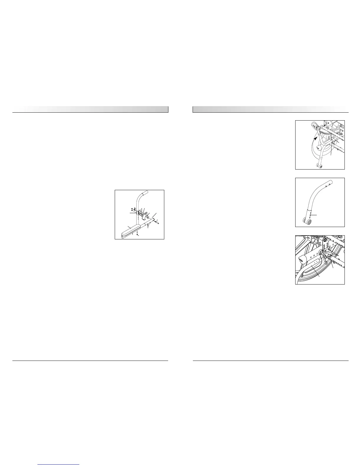
I. ADJUSTABLE LOCKING FLIP-UP ARMRESTS
1. Flip up and down
a. Release the upper securing lever (B).
b. Flip the armrest back, it remains attached to
the back post.
c. Move armrest down into place.
d. The lever (B) locks itself in position automati-
cally.
2. Height Adjustment
a. Loosen bolts (C, D) and remove flip-back tube.
b. Loosen bolts (E, F) and remove clamp (J).
c. Move the clamp (J) up or down to the desired
position.
d. Tighten bolts (E, F).
e. Install the flip-back tube back in place and
tighten bolts (C,D).
f. Repeat the process for the other armrest.
3. Angle-Adjustment
a. Loosen bolt (D).
b. Set armrest at desired angle using preset holes
in armrest angle plate.
c. Tighten bolt.
4. Length-Adjustment (optional)
a. Remove foam grip or armpad (A) from armrest.
b. Loosen screw (G) in the adjustable flip-up tube.
c. Reposition the sleeve (I) at the desired length.
d. Re-tighten the screw (G).
e. Put foam grip or armpad back in place.
G
C
A
J
A. Armrest Pad
B. Upper Securing Lever
H. Flip-back tube
I. Sleeve
J. Clamp
D
B
E
F
Adjustable Locking Flip-Up
H
I