108833 Rev. C
17
S-636 / S-646
IX. SET-UP, ADJUSTMENT, & USE
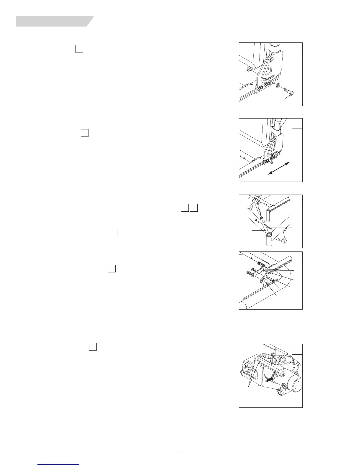
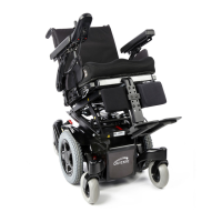
K. BACKREST
A backrest angle-adjustment is standard on the Trax Seat Frame.
1. Adjustment on Trax Seat Frame
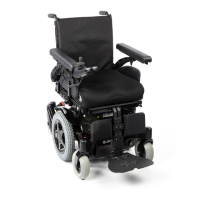
a) Remove the securing bolt (A) on the sides of the backrest hinge plate.
b
) Set at desired angle. There are ten holes (in 4º increments) to choose from.
c) Reinstall the front bolt and tighten both bolts securely.
L. SEAT DEPTH
The seat depth can be adjusted continuously along the seat rail.
a) To adjust, loosen the four bolts (B) from each side of the backrest pivot plate.
b) Reposition the backrest to the desired position.
c) Retighten bolts on each side of the backrest pivot plate.
M. SEAT HEIGHT AND ANGLE ADJUSTMENT
Adjusting the seat height can be done both at the front and the rear of the seat. Seat angle
can also be varied through front and rear seat height adjustments.
1. Front Seat Height Adjustment
a) Remove bolt (C) in the seat height strut (D). Adjust the upper and lower tube until the
desired front seat height is achieved. Each upper hole is 1" apart. Each lower hole is
1/2" apart. This allows 1/2" seat height increments.
b) Replace the bolt and secure the locknut.
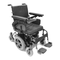
2. Rear Seat Height Adjustment
a) Remove bolt (E).
b) Loosen bolt (F), but do not remove.
c) Adjust seat height to match one of three positioning holes (I). Each hole is 1" apart.
d) Refasten bolt (E) and retighten bolt (F).
e) To achieve 1/2" increments adjust position bolt (G) to either hole (H) and refasten.
N. WHEEL LOCKS
Wheel locks are installed by Sunrise when requested on the Quickie S-636/S-646.
1. Mounting
The wheel lock mounts to the motor mount. Use a torque setting of 100 in./lbs when adjust-
ing wheel locks.
a) Loosen bolts (J).
b) Slide mounting bracket toward rear wheel until clamp embeds into tire to prevent
wheel movement when in locked position.
c) Tighten screws.
NOTE– Wheel lock adjustment will be done through the drive-wheel spokes.
11
12
13 14
13
14
15
A
B
move back
o
r forward
l
oosen all 4
C
D
G
H
F
E
I
11
12
13
14
J
15