Do you have a question about the Quickie QM-7 Series and is the answer not in the manual?
Explains the multimeter, its probes, and connection ports for electrical testing.
Defines common electrical symbols used with multimeters for accurate readings and circuit analysis.
Outlines essential safety guidelines for handling equipment and batteries, including personal protection.
Provides instructions for safe operation and handling of battery chargers, emphasizing electrical safety.
Explains sources of EMI, its potential effects on the power chair, and user safety precautions.
Lists common sources of EMI like handheld radios, mobile devices, and broadcast towers.
Describes different battery types suitable for wheelchairs and factors affecting battery size selection.
Provides guidance on correctly installing wheelchair batteries, emphasizing harness connection.
Illustrates and explains the pinouts and connections for the VR2 joystick and charger ports.
Describes the function of buttons on the R-NET LED remote controller, including speed and tilt controls.
Details the R-NET controller with display, covering mode, profile, speed adjustments, and toggle functions.
Shows pinouts for the R-NET harness, charger port, and motor connections for the controller.
Details the connection setup for the VR2 dual attendant system, including troubleshooting for faults.
Presents wiring diagrams for the VR2 system, including power module connections and bus connections.
Illustrates R-Net power module and bus connections for various seating configurations.
Diagrams the switch-drive systems for Tilt-only and Lift-only configurations with VR2 and R-NET.
Explains the wiring for 3-axis actuator drivers for Tilt and Lift functions in VR2 and R-NET systems.
Details wiring diagrams for 2-axis and Thru-Drive actuator systems for VR2 and R-NET.
Shows wiring for R-NET multi-actuator systems with and without lift/tilt, detailing actuator connections.
Illustrates system connections for R-NET specialty controls, including attendant controls and external devices.
Depicts battery types (Group 24/22) and installation methods, including harness routing and cable ties.
Covers battery diagnostics, servicing, replacement, and voltage testing procedures for VR2 systems.
Explains the meaning of VR2 controller display indicators like speed ripples, flashes, and battery gauge states.
Guides on troubleshooting left motor wiring trips and right motor disconnection errors using resistance tests.
Addresses faults related to charger connection, joystick trips, speed profile errors, and control system issues.
Explains troubleshooting for solenoid brake trips, high battery voltage, and general battery faults indicated by bars.
Steps to diagnose and resolve issues when the R-NET power chair fails to turn on, checking battery voltage and components.
Verifies bus cable mating and checks battery voltage at the power connector for R-NET system issues.
Guides on testing battery voltage at connectors and checking the fusible links in the battery harness.
Demonstrates isolating an R-10 fault, identifying a disconnected right motor and referring to error code tables.
Troubleshoots why the power chair won't drive at full speed, relating it to tilt position and a creep speed micro-switch.
Details testing the creep micro-switch for proper operation and continuity to diagnose speed issues.
Addresses issues where the chair fails to engage creep speed when tilted, checking the micro-switch signal.
Tests voltage and continuity at the tilt/lift actuator connectors and cables for troubleshooting.
Provides specific tests for tilt actuator motor windings and micro-switch continuity in different tilt positions.
Explains how to analyze battery load test results, including rapid voltage drops and slow drops indicating battery issues.
Describes how to check individual battery voltages, interpret readings for charged, overcharged, or discharged states.
Details inspecting motor brushes for wear, leads for overheating, and commutators for cleanliness and arcing.
Explains how to measure resistance for the park brake assembly and motor brush assembly using a multimeter.
Provides step-by-step instructions for accessing and removing wheelchair batteries, emphasizing safety.
Details the correct process for installing batteries, including harness attachment and torque specifications.
Outlines steps for disconnecting power and removing the motor and wheel assembly from the chair.
Describes the process for removing components on units equipped with a mechanical brake.
Explains how to access and disconnect the control module by removing its cover and connectors.
Guides on removing and replacing caster wheels and their stems, detailing the nuts and bolts involved.
Instructions for removing gas springs, including wheel removal, lower holding bolt, and top holding bolt.
Details removing the seating system, disconnecting the tilt actuator connector, and unfastening nuts.
Instructions for removing the rear shroud and gaining access to the ISM control module for recline actuator removal.
Details removing the shear actuator after recline actuator removal, including disconnecting ISM box and mounts.
Outlines steps for removing the elevate actuator by disconnecting wires from the ISM control box and lift module.
Guides on adjusting seat width for ASAP II seating systems, involving loosening bolts and sliding plates.
Explains how to adjust legrests using hex keys and wrenches, moving footrest extensions and calf pads.
Details operating the 4-way switch or joystick for powered legrest adjustments on the center mount.
Explains that back-rest angle is set by programming; no mechanical procedures are required.
Guides on adjusting seat height using threaded bolts on the front bracket, referencing a height matrix.
Details adjusting seat height using rear bracket bolts and referencing shroud removal for access.
Covers recline angle programming and pivot point adjustments for seat/back height.
Explains how to adjust seat-back depth by moving mounting brackets along the seat-pan track.
Guides on adjusting armrest angle and height, including kid's and user-in-chair adjustments.
Describes 2-axis and 3-axis actuator boxes used for lift, tilt, and power legrest functions.
Explains operating powered legrests and seat functions using VR2/R-Net controls and multi-axis boxes.
Details the inhibit schemes for drive systems and ISM actuators based on switch states and module connections.
Defines symbols displayed on R-NET controllers and Omni interfaces, indicating system status and modes.
Provides a matrix for calculating seat height adjustments based on chair configuration and STFH positions.
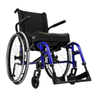
| Maximum Speed | N/A (manual wheelchair) |
|---|---|
| Battery | N/A (manual wheelchair) |
| Range | N/A (manual wheelchair) |
| Overall Length | 41" |
| Armrests | Height Adjustable, Removable |
| Footrests | Swing-away |
| Seat Widths | 16", 18" |
| Seat Depths | 16", 18" |