QM-7 SERIES SERVICE MANUAL
PAGE 4.2
JANUARY 2012 SUNRISE MEDICAL
Section 4
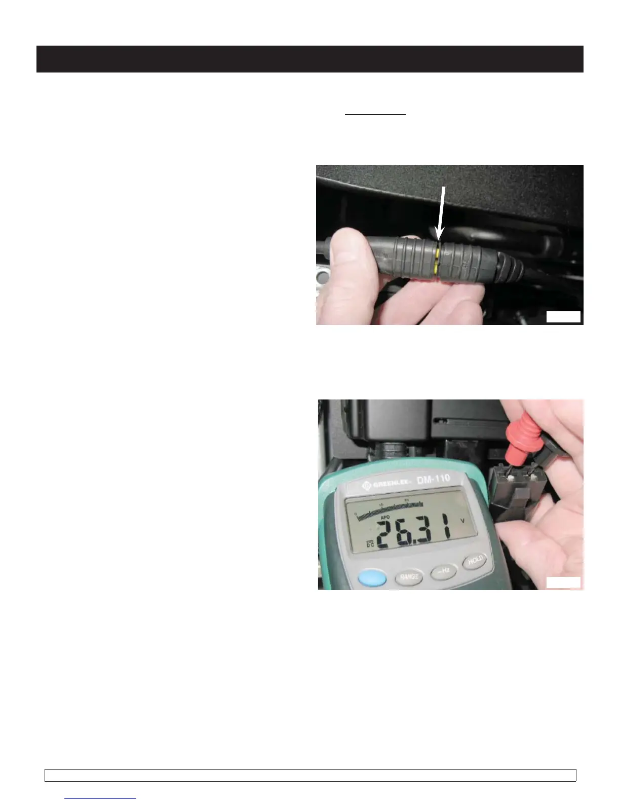
4. Verify that the bus cables are correctly mated
between the hand control and the control module
(figure 4.2.1).
A
Note: The connector shown in (figure 4.1.3) is mated incorrectly. The connectors are designed
to visually indicate when they are not mated correctly. If yellow is showing between the halves
(A), push them closer together until only black is visible. Retest as necessary.
fig 4.2.1
5. Disconnect the power connector from the
control module, and use a Multimeter to check for
battery voltage at the connector. If a good voltage
is present, with batteries fully charged, (figure
4.2.2), then replace the control module. Retest
as necessary.
fig 4.2.2
Note: For the next step, locate the power connector plug. It is a large 2-pin connector between
left and right motor cable.

 Loading...