QM-7 SERIES SERVICE MANUAL
PAGE 3.2
JANUARY 2012 SUNRISE MEDICAL
Section 3
Battery Connection Test
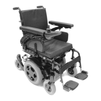
1. Check that the female VR2 Bus plug on
the chair has voltage. Set the meter to DC volts
and measure pins 4 (using the red lead of the
meter) and 1 (using the black lead of the meter)
as shown in (fig 3.2.1)
Fig 3.2.1
Fig 3.2.2
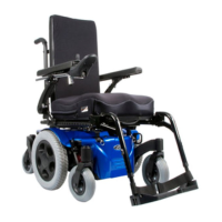
2. If the voltage meter reads full voltage, then
replace the joystick module
If the voltage meter reads zero voltage, measure
the corresponding pins on the VR2 controller as
shown in (fig 3.2.2).
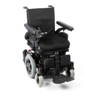
If the voltage meter reads full voltage, then
replace the jumper cable. If the voltage meter
reads zero, then measure the Battery Connector
as shown in (fig 3.2.3). If the voltage meter reads
full voltage, replace the controller, or proceed to
the next step.
Fig 3.2.3
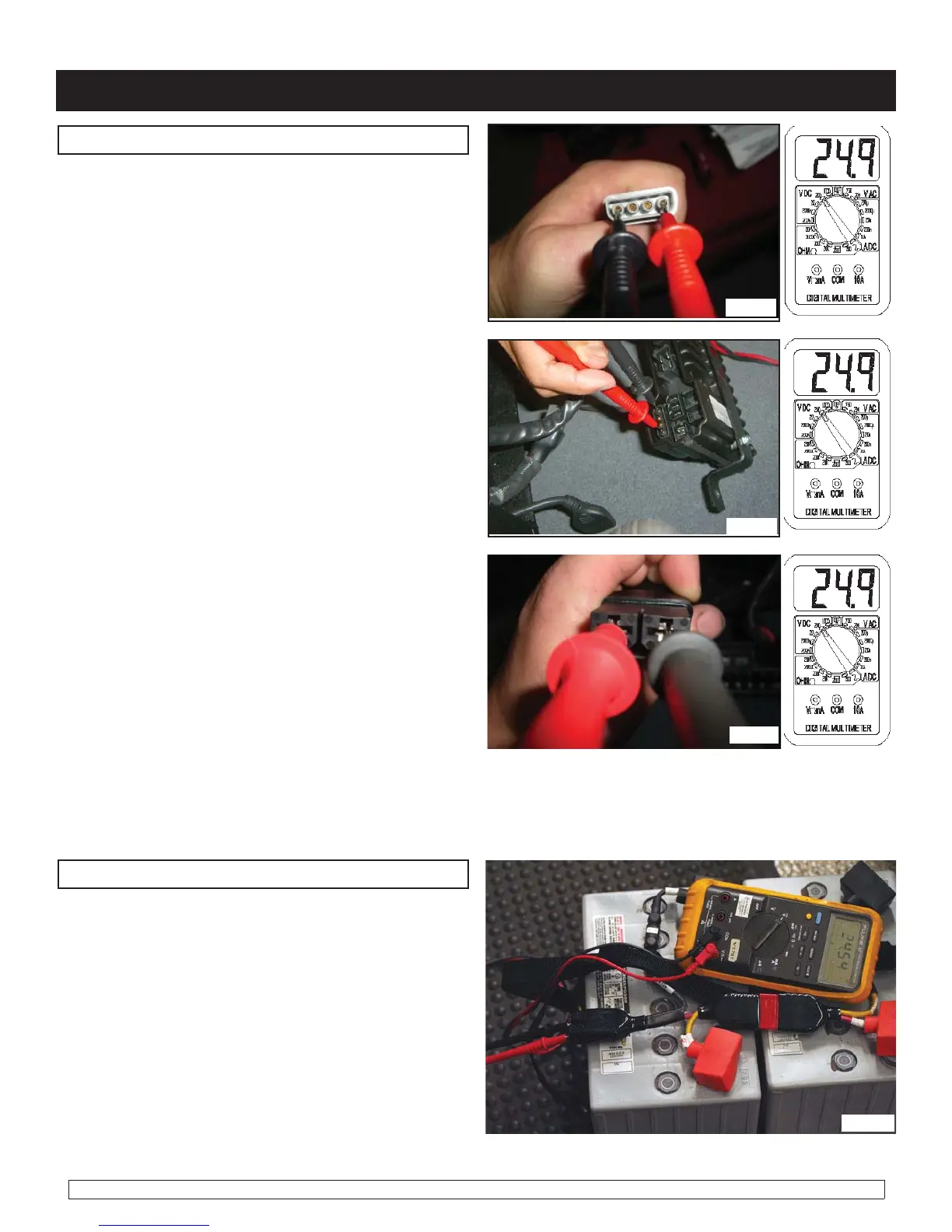
Check Battery Wire Harness
1. Check that the battery wire harness has the
correct polarity. Set the meter to dc volts and
measure the connector with the red lead on the
positive terminal, and the black lead on the nega-
tive terminal as shown in (figure 3.2.4). If the
voltage is absent Replace the Main Battery wire
Harness. If the polarity is reversed correct bat-
tery wiring.
Note: For access to batteries, refer to beginning of Section 7 (Battery Access/ removal)
Fig 3.2.4
 Loading...