QM-7 SERIES SERVICE MANUAL
PAGE 4.11
JANUARY 2012SUNRISE MEDICAL
Section 4
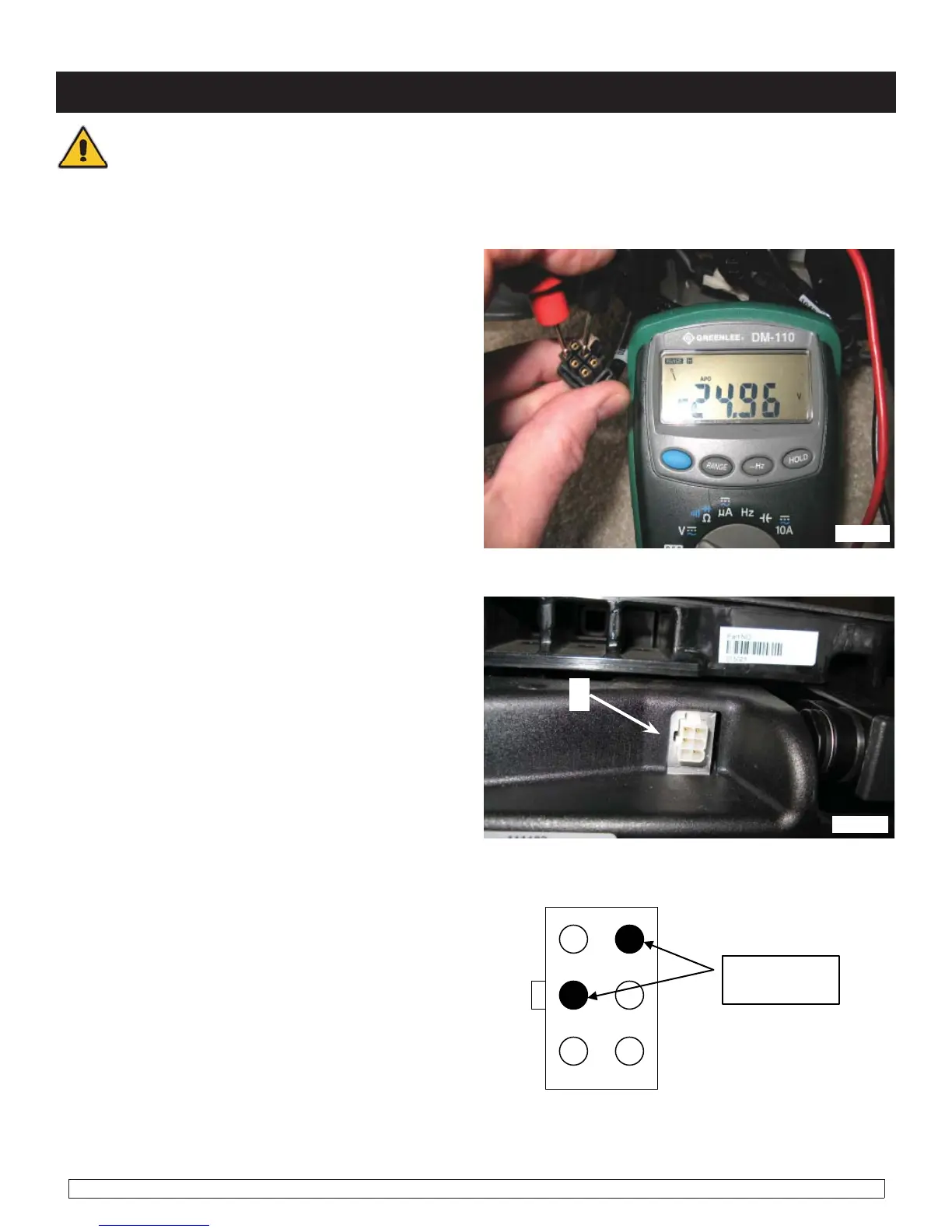
Warning: Use caution in the next step. Do not short the leads of the Multimeter together or
damage may occur to the control module.
6. At the 6-pin connector on the cable leading to
the control module, verify that battery voltage is
present between the indicated pins (fi gure 4.11.1).
Note: The polarity of the voltage is not important
since it is reverses when the opposite direction is
selected.
8. At the 6 pin connector (B) (fi gure 4.11.2) on
the rear of the tilt, check continuity between the
indicated pins (fi g. 4.11.3).
fig. 4.11.1
fig. 4.11.2
1 to 3 ohms
Voltage to
the actuator
B
fig. 4.11.3
7. If voltage is not present, replace the cable
leading to the control module. If this does not
solve the problem, replace the control module.
Refer to Control Module Removal section of this
manual. Retest as necessary.

 Loading...