3.
Feed control cables, neutral start safety switch wir-
ing harnesses and trim harness thru control base
and opening in mounting panel (cut previously) and
set control in position.
AWARNING
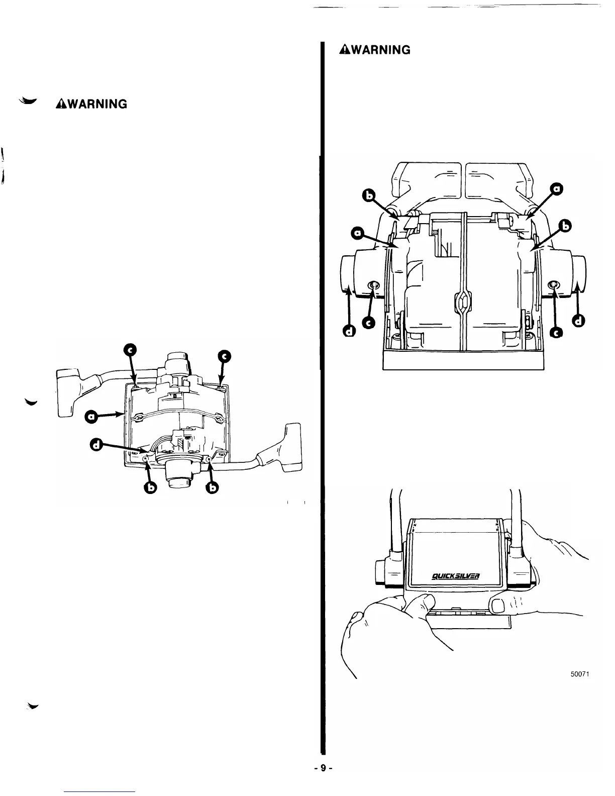
Trim wiring harness must be positioned with plastic
sleeves (on harness) at the exact location shown to
keep harnesses from being pinched or cut by mounting
brackets.
4.
5.
6.
Position trim harness so that plastic sleeve is at the
exact location shown.
Insert mounting screws (4) thru control mounting
brackets, control base and mounting panel. Tighten
securely.
Move one control handle to full “Forward” position
and one control handle to full “Reverse” position.
Apply a slight amount of downward force on each
handle to align the 2 control modules, then torque
locknuts (which secure mounting brackets on con-
trol modules together) to 35 Ibs. in.
(4
N.m.)
50058
a
-
Control Base
b
-
Control Mounting Screws
c
-
Locknuts (Torque to 35 lb. in.)
d
-
Plastic Sleeve
AWARNING
Set screws in control handles must be torqued to speci-
fication. Failure to tighten set screws securely could
allow control handles to disengage, with subsequent
loss of throttle and shift control.
7.
Move control handles to allow access to set screws.
Torque set screws to 60 Ibs. in. (7 N.m.)
50058
a
-
Detent Adjustment Screw
b
-
Control Handle Friction Screw
c
-
Set Screw
d
-
“Throttle-Only” Button
8. Install cover by snapping into control base.