Operation
1.
2.
3.
4.
5.
6.
The Control handles
feature full gear shift and
throttle. Always shift with a firm, quick motion.
Approximately the first 40-degrees of control han-
dle travel (“Forward”
and “Reverse”) shifts the
engines. Remainder of control handle movement
advances the throttle. DO NOT try to shift into
“Reverse”, if control is used with an outboard and
outboard is not running. Forcing shift lever (on an
outboard) under this condition may result in dam-
aged shift mechanism.
“Throttle-Only
button (located in the center of each
control handle hub) allows engine throttle advance-
ment without shifting the engines. This is done by
disengaging the shift mechanism from the control
handle. “Throttle-Only” buttons can be depressed
only when control handles are in neutral, and
should be used only to assist in starting the engines.
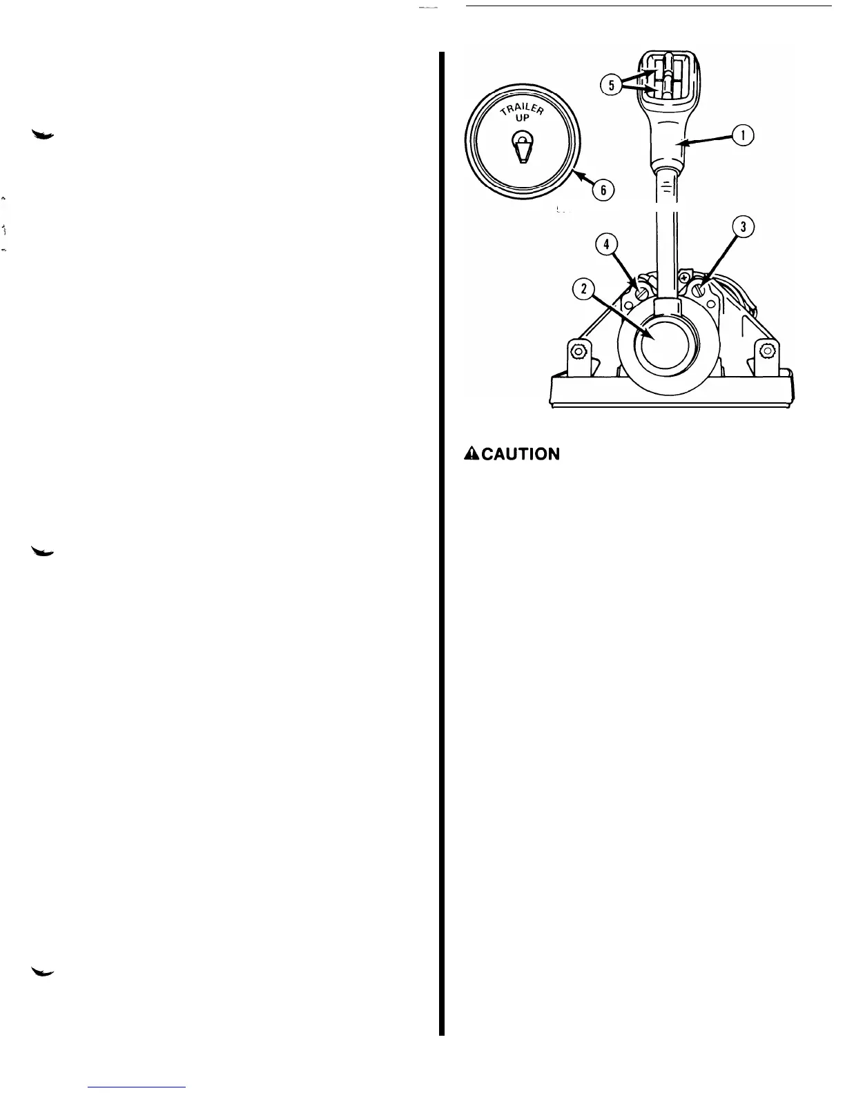
Detent adjustment screw
is located in each control
module. The detent adjustment screws will increase
or decrease the effort necessary to move control
handles in or out of neutral position. To increase
detent, thread detent screws “in” (clockwise.) To
decrease detent, thread detent screws “out” (coun-
terclockwise.) (DO NOT thread detent screws all-
the-way out.)
Control handle friction screw
is located in each
control module. The control handle friction screws
are an adjustment that sustains a set engine speed
without the driver’s hand holding onto the control
handles. To increase control handle friction, thread
friction screws “in” (clockwise). To decrease con-
trol handle friction, thread friction screws “out”
(counterclockwise.) (DO NOT thread friction
screws all-the-way out.)
Trim Switch:
Push toward “UP” to trim power pack-
age out or push toward “DOWN” to trim in.
Trailer Switch:
Used to raise power package to
desired height for trailering, launching, beaching or
shallow water operation.
50126
I II
\
/
50063
ACAUTION
If engine will be operated in shallow water with lower
unit trimmed follow these precautions:
1. Do not operate engine above idle RPM. (When
lower unit is trimmed beyond side supports the
lower unit will have no side support).
2. Check that water level is above water intake ports.
(should water level fall below water intake ports,
damage from overheating or water pump impeller
damage could occur.)
NOTE: If the trim switch remains pushed toward the
“DOWN” position, after unit reaches its end of travel,
an overload cut-out switch will open and pump motor
will stop. To prevent cut-out switch from opening, it is
recommended that trim switch be released as soon as
unit reaches end of travel. If cut-out switch should
open, do not depress switch or button for approxi-
mately one minute. After this period of time, cut-out
switch will close (reset itself) and pump again may be
operated.
-13-