Do you have a question about the Quietside QSCE-123 and is the answer not in the manual?
Make sure to have professional after-sale service persons install the units before use.
Safety precautions for operating the air conditioner, including electrical safety.
Avoid sunlight, minimize heat, do not use combustion, adjust air direction, avoid water, check supports.
Contact dealer for removal/repair. Stop operation and cut power for abnormal occurrences.
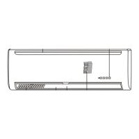
Details of air return grid, fins, outlet, filter, and drain tube.
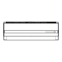
Details of air inlet and discharge vent.
How to open and close the unit for operation, including emergency key.
Explanation of running, sleeping, timer, and temperature/malfunction code indicators.
Explanation of ON/OFF, MODE, SET TEMPERATURE, FAN SPEED, TURBO, TIMER, SWING, SLEEP buttons.
Explanation of temperature, AUTO, COOLING, DRYING, HEATING, FANING, SWING, TIME indicators.
Describes how the remote controller sends signals to the air conditioner unit.
Steps to select modes like AUTO, COOL, DRY, HEAT, FAN and set temperature.
How to use the TURBO mode for maximum cooling and heating.
Methods for manually adjusting airflow direction or using auto swing.
How to set the timer for turning the unit on or off.
How sleep mode reduces operation sound and adjusts temperature.
How the unit absorbs outdoor heat to heat the room.
Explanation of the automatic defrosting function for the outdoor unit.
Checks and preparations before the air conditioner is used for the season.
Maintenance tasks during the operating season, focusing on air filter cleaning.
Maintenance and storage procedures after the operating season.
Checks to perform if the air conditioner is not operating at all.
Checks for poor cooling/heating performance, including filters and windows.
Situations that require immediate contact with a professional.
Explanations for common operational behaviors like restart delay, air blow timing, and noise.
Important considerations for electrical wiring and connections.
Wiring diagrams for QSCE/QSCC models.
Considerations for environment, cable specs, grounding, and qualified electricians.
Connecting indoor wire connector with outdoor probe wire connector for heat pump defrosting.
Guidance for qualified HVAC contractors on installation and maintenance.
General safety warnings and precautions for installation and operation.
Explanation of danger and warning symbols indicating important safety information.
List of items supplied by the installer for the unit.
Considerations for different applications like server rooms, offices, and residential spaces.
Guidelines for determining the best location for mounting the indoor unit.
Guidelines for positioning the outdoor unit and required clearances.
Information on optional controls like Low Ambient Controller and Condensate Pump.
Instructions for unpacking the indoor and outdoor units and their accessories.
Guidelines for selecting the installation area for the indoor unit, considering clearances.
Procedure for drilling the hole for line sets and condensate drainage.
Instructions for securely mounting the bracket for the indoor unit.
Steps for connecting refrigerant lines, condensate hose, and wiring.
How to hang and secure the indoor unit onto the mounting bracket.
Guidelines for positioning the outdoor unit and required clearances.
Detailed instructions for connecting the refrigerant lines between indoor and outdoor units.
Procedure for evacuating the refrigerant system to remove moisture.
Instructions for connecting the main power wiring, including breaker sizing.
Instructions for connecting control wiring between indoor and outdoor units, including defrost sensor.
Instructions for connecting the condensate hose and ensuring proper drainage.
Steps to open service valves and release refrigerant into the line set.
Table for calculating additional refrigerant charge based on line set length.
Expected pressures and temperatures during cooling operation.
Expected pressures and temperatures during heat pump operation.
Electrical circuit diagram for QSCC-093/QSCC-123 models.
Electrical circuit diagram for QSCC-183/QSCC-243 models.
| Brand | Quietside |
|---|---|
| Model | QSCE-123 |
| Category | Air Conditioner |
| Language | English |