Section 2- Description
*QSVI Vacuum Pumps
*Principals of Vacuum Pump Operation
*Air Flow
*F1uidFlow & Cooling System
*Fluid Coolers
*Air/Fluid Reservoir & AirlFluid Separator
Element
*Auto Dual With Modulation
*Auto Demand-Optional
*Electrical System
*Indicators & Gauges
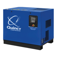
QSVI Vacuum Pumm
The QSVI line of rotary screw vacuum pumps are
single stage, positive displacement, fluid flooded,
helical screw type units. They consist essentially of two
rotors that resemble worm gears. The male rotor is
direct driven through a flexible coupling on all QSVI’S
excxmtthe CISVI40. The male rotor has four lobes that
suction and discharge ends. The electric motor, airend
and associated equipment are mounted on a welded
structural frame.
Radial loads are carriedon cylindrical roller bearings
on the power or suction end of the vacuum pump.
Radial and axial loads are carried on tapered roller
bearings at the discharge end of the vacuum pump.
Fluid circulation is maintained by an external fluid
pump directly driven by the rotor.
Princi~les of Vacuum Purer) Oueration
As the rotors turIL air is drawn into the rotor housing
through the inlet port. This volume of trapped air
extends the entire length of the two rotors initially and
is prevented from escaping by the unported area of the
rotor housing wall. As rotation continues, the air at the
inlet side is carried to the discharge side and forced out
the discharge port, the discharge pipe, and into the
air/fluid reservoir where it is discharged to the
atmosphere through a fluid separator element. The
mesh with six grooves in the female rotor. Both rotors
compression cycle of a rotary vacuum pump is a
are contained in a rotor housing that has two parallel
continuous process from intake to discharge. The airend
axis and adjoining bores. There is an air inlet port
consists of two rotors in constant mesh housed in a
,..
located at the power input end of the vacuum pump and
cylinder with two parallel adjoining bores. All parts are
a discharge port located at the opposite end. Both
machined to exacting tolerances.
rotors are mounted in anti friction bearings at both the
m
MALE
“Oroa
Olsclunr,c
\
-.7
c .2, SCMARGC
,—
Compression Cycle
..
Page 30
.———
———.
———e.. . . . . . . . . . .,-. _. _
—..-——..-..—.—————”——-———
,.— —.,
.-, - -,
 Loading...