Air Flow
During pump operation, a vacuum is produced at the
pump inlet. Air entering flows through the air inlet
valve into the rotor housing where it is compressed,
then discharged within the air/fluid reservoir. The air
discharged from the pump contains fluid which is
separated from the air as it passes through a fluid
separator located within the air/fluid reservoir. The
gas, now at near atmospheric pressure, is exhausted
through the discharge pent on the reservoir housing.
The air/fluid resemoir is equipped with a safety valve to
protect the system in the event of excessive restriction
to the air flow in the separator element or the discharge
system.
Fluid Flow & Cooling System
The fluid in the system serves three functions: it
lubricates the bearings and the rotors, it seals rotor
clearances to improve etllciency, and it removes heat
from the gas as the gas is being compressed, thus
lowering the discharge temperature.
Fluid is pumped out of the air/fluid reservoir through a
fluid filter and then into the airend. In the airend, some
of the fluid is diverted directly to the bearings through
internal passages to insure positive lubrication to the
bearings, the remainder of the fluid is injected into the
early stage of the evacuation cycle to seal clearances
and lubricate the rotors.
Fluid Coolers
Removal of the heat from the fluid is achieved with
either an air-cooled or a water-cooled heat exchanger.
The air-cooled fluid cooler is a tinned tube unit. A
continuous supply of cool air is forced across the tins
and tubes by a fan mounted on a separate drive motor.
Minimum fluid injection temperature is controlled by a
thermal mixing valve which permits a controlled
amount of hot fluid to mix with the cooled fluid before
entering the vacuum pump. The water-cooled fluid
cooler is of shell and tube construction. Minimum fluid
injection temperature is controlled by a water
regulating valve which senses the fluid temperature
entering the vacuum pump and regulates the cooling
water flowing through the fluid cooler.
AirfFuid Reservoir& AirfFluid Separator Element
The air/fluid reservoir serves as a fluid reservoir and
contains the air/fluid separator element. The discharge
pipe from the vacuum pump enters the reservoir at a
point below the normal fluid level and then turns
upward inside the reservoir. The air/fluid mixture is
discharged into the reservoir above the fluid level and
impinges on the underside of the separator element.
The air/fluid reservoir is provided with a fluid filler
opening and fluid level gauge.
As the air/fluid mixture impinges on the bottom of the
fluid separator element, most of the fluid separates from
the air and drops to the bottom of the reservoir. The
remaining fluid, suspended in the air stream, passes
through the media of the separator element and is
removed from the discharge air stream. The fluid is
then returned to the vacuum pump by means of a
scavenging line connected from the bottom of the
air/fluid separator element to the inlet housing.
It should be noted that the separator element is sized
larger for a vacuum pump than it would be for the
equivalent displacement compressor, and only Quincy
approved separator elements should be used.
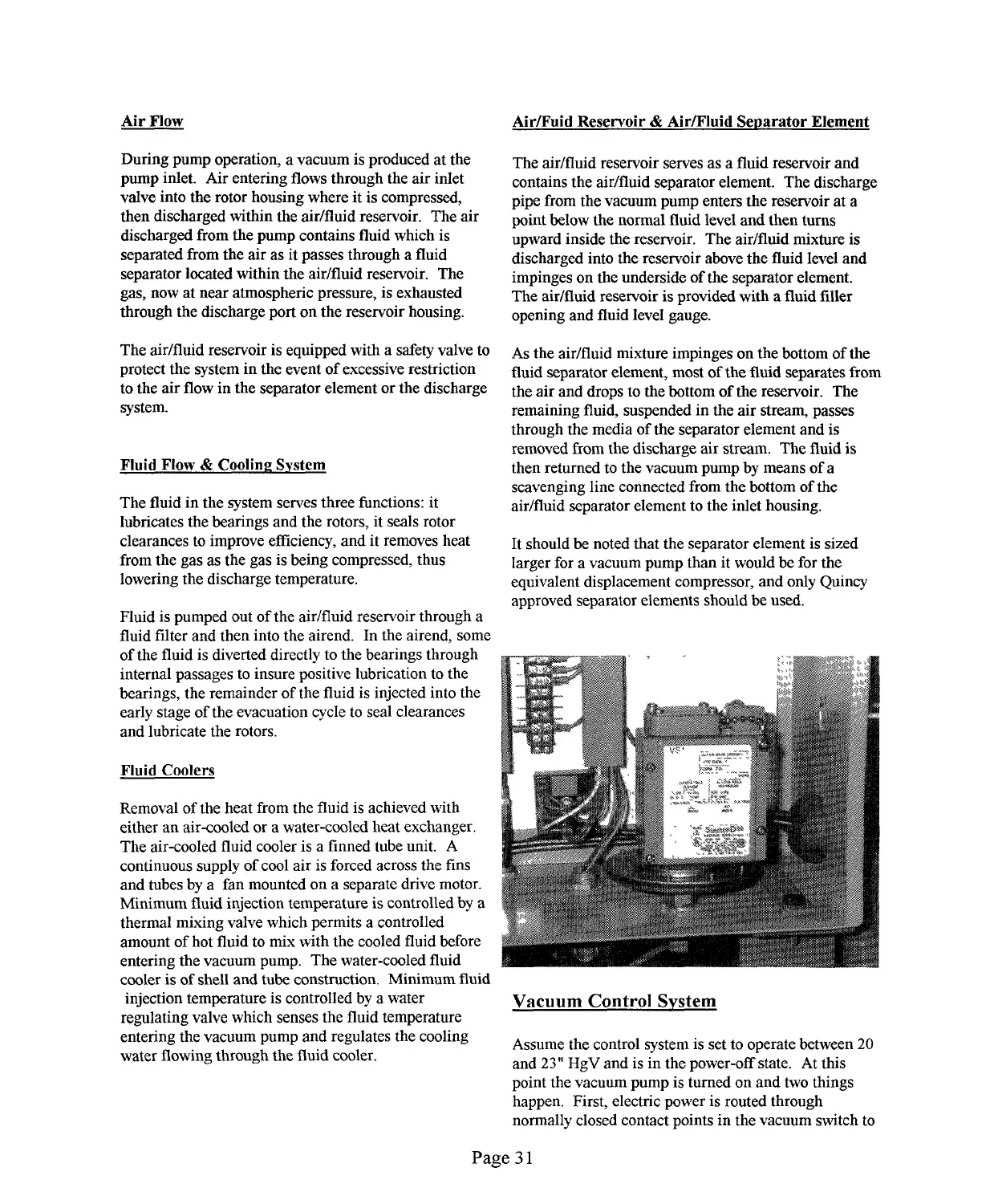
Vacuum Control System
Assume the control system is set to operate between 20
and 23” HgV and is in the power-off state. At this
point the vacuum pump is turned on and two things
happen. First, electric power is routed through
normally closed contact points in the vacuum switch to
Page 31
-...-.. ------ - . -
..----
., .. ..........— -....-. -- .. .. . ...
 Loading...