the normally open solenoid valve causing it to shift
.-
closed from the open position. Second, the inlet valve
permits air to flow from the vacuum system to the
vacuum pump inlet, where it is compressed to
atmospheric pressure and discharged through the
airhluid reservoir.
The control system remains in this state until the
vacuum level in the plant system increases to 20” HgV,
at which point the vacuum regulator permits more
vacuum to be applied to the inlet valve air cylinder
causing it to gradually close the inlet valve until the
amount of air permitted into the vacuum pump is equal
to the amount of air being leaked into the plant vacuum
system through use. If vacuum system usage continues
to decrease causing the vacuum level to increase to 23”
HgV, the vacuum switch trips, opening the normally
closed contacts and stopping power flow the solenoid
causing it to shift to the normally open position.
This permits enough air to flow (regulated by a .033”
orifice) from the inlet valve air cylinder through the
solenoid to the vacuum pump inlet to close the inlet
valve completely. This action keeps the vacuum level
in the system from rising above the maximum set point,
23” HgV, for example here.
.- %
The .025” orifice is sized to permit the air cylinder to
open when the vacuum signal from the vacuum
regulator or solenoid valve ceases, while still restricting
air flow into the control piping network to a level such
that the vacuum regulator remains effective during
operation. The .033” orifice is sized to work together
with the .025” orifice such that when the solenoid valve
opens, only enough vacuum is provided at the air
cylinder to close it . This enhances the responsiveness
of the control system. The .078” orifice keeps the air
cyIinder from oscillating.
The vacuum pump is now running with a fully closed
inlet valve. When vacuum level in the system drops to
the lower set point, 20” HgV in this case, the switch
closes, shifting the solenoid valve to the closed position
and permitting the inlet valve to open. This cycle
continues as required by vacuum system usage, and a
vacuum level of 20” to 23” HgV is maintained in the
vacuum system.
If the vacuum pump stops during operation, either
manually from the panel, or automatically due to a high
temperature condition, the
inlet valve will not act as a
check valve
to prevent air from entering the
vacuum system through vacuum pump.
What has been described here is the operation of the
control system over a 20” to 23 “ HgV vacuum range,
with lower set point of 20” HgV, an upper set point of
23” HgV, and a 3” HgV differential. The control
system is designed to operate with an upper set point of
10” HgV to 29.6” HgV at sea level barometer (29.92 in.
Hg).
-.
Page 32
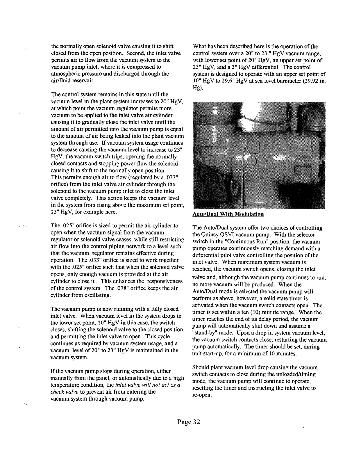
Auto/Dual With Modulation
The Auto/Dual system offer two choices of controlling
the Quincy QSVI vacuum pump, With the selector
switch in the “Continuous Run” position, the vacuum
pump operates continuously matching demand with a
differential pilot valve controlling the position of the
inlet valve. When maximum system vacuum is
reached, the vacuum switch opens, closing the inlet
valve and, although the vacuum pump continues to run,
no more vacuum will be produced. When the
AutolDual mode is selected the vacuum pump will
perform as above, however, a solid state timer is
activated when the vacuum switch contacts open. The
timer is set within a ten (10) minute range. When the
timer reaches the end of its delay period, the vacuum
pump will automatically shut down and assume a
“stand-by” mode. Upon a drop in system vacuum level,
the vacuum switch contacts close, restarting the vacuum
pump automatically. The timer should be set, during
unit start-up, for a minimum of 10 minutes.
Should plant vacuum level drop causing the vacuum
switch contacts to close during the unloaded.himing
mode, the vacuum pump will continue to operate,
resetting the timer and instructing the inlet valve to
re-open.
. ..-.—-—.._ —...__. __. _...—__ .__— ____ ,_. .._ ...__. .- ,___>. ___7.. _..~__
.A ,.>’...-. .
——
—---- . . .
. .
- —---- -r- .
.—
. e..- ._. . . . . . .
 Loading...