>-
Sedon 7- Service
Adjustments
*Differential Pilot Valve
*Vaauun Switch
*Water Temperature Regulating Valve
*Coupling Alignment
*Correcting Angular Mkaligoment
*Water-Cooled Heat Exchanger
Differential Pilot Valve
Open a manual vent valve on the inlet to the vacuum
pump and start the unit. By manual regulation slowly
close the valve, allowing the system pressure to reach
the desired vacuum level. Adjust the screw on the
bottom of the diEerential pilot valve so that a slight
vibration can be detected at the point of desired system
modulation. When this vibration is felt, air is
beginning to pass through the pilot valve to the air
cylinder on the inlet valve, causing the valve to
modulate toward its closed position, thereby, reducing
the volume of air being drawn in to the pump.
To raise pressure turn the adjusting screw in
(clockwise). To lower pressure, turn the screw out
(counter ckdcvvise). Maximum vacuum under
modulation is 29.6” HgV. for the QSVI vacuum pumps
(29.9” HgV without modulation).
Vactmm Switch
The pressure switch determines at what pressure the
vacuum pump will load and unload. Standard factory
settings are listed in the QSVI Specit%xtions. If a
lower setting is desird adjust the differential pilot
valve first and set the pressure switch cut-out point to
no less than 2“ HgV differential. That adjustment is
made by turning the wheel clockwise to increase the
eut-inknt-out pressure and counter clockwise to lower
Cut-irdcut-out pressure. The vacuum switch should
unload the vacuum pump by the time it reaches the 20°/0
load point.
Water Temperature Remdatin~ Valve (water-cooled
units)
The water temperature regulating valve senses fluid
temperature and opens or closes, regulating water flow
fkom the unit. It is factory set to maintain 160° F fluid
,.”..
injeetion temperature as shown by the fluid inlet
temperature gauge. Due to cMYerentincoming water
temperature andlor pressures at the customers location,
valve adjustment should be checked during start-up to
maintain 160”F fluid inlet temperature. To increase
fluid temperature, decrease water flow by turning the
adjusting screw clockwise. To decrease fluid
temperature, increase water flow by turning the
adjustment screw counter clockwise.
Cou~lin~ Ali@ment
Compressor and motor bearing life can be maximized
only when both components are in alignment to each
other. Prior to new unit start-up or after any vacuum
pump or motor change the drive alignment must be
checked. If the vacuum pump is ever accidentally
knocked out of place or relocated, the drive alignment
must be checked, Note! Some QSVI models are
permanently aligned and the above statement wiIl
not apply to those models. Check your machine for
alignment type.
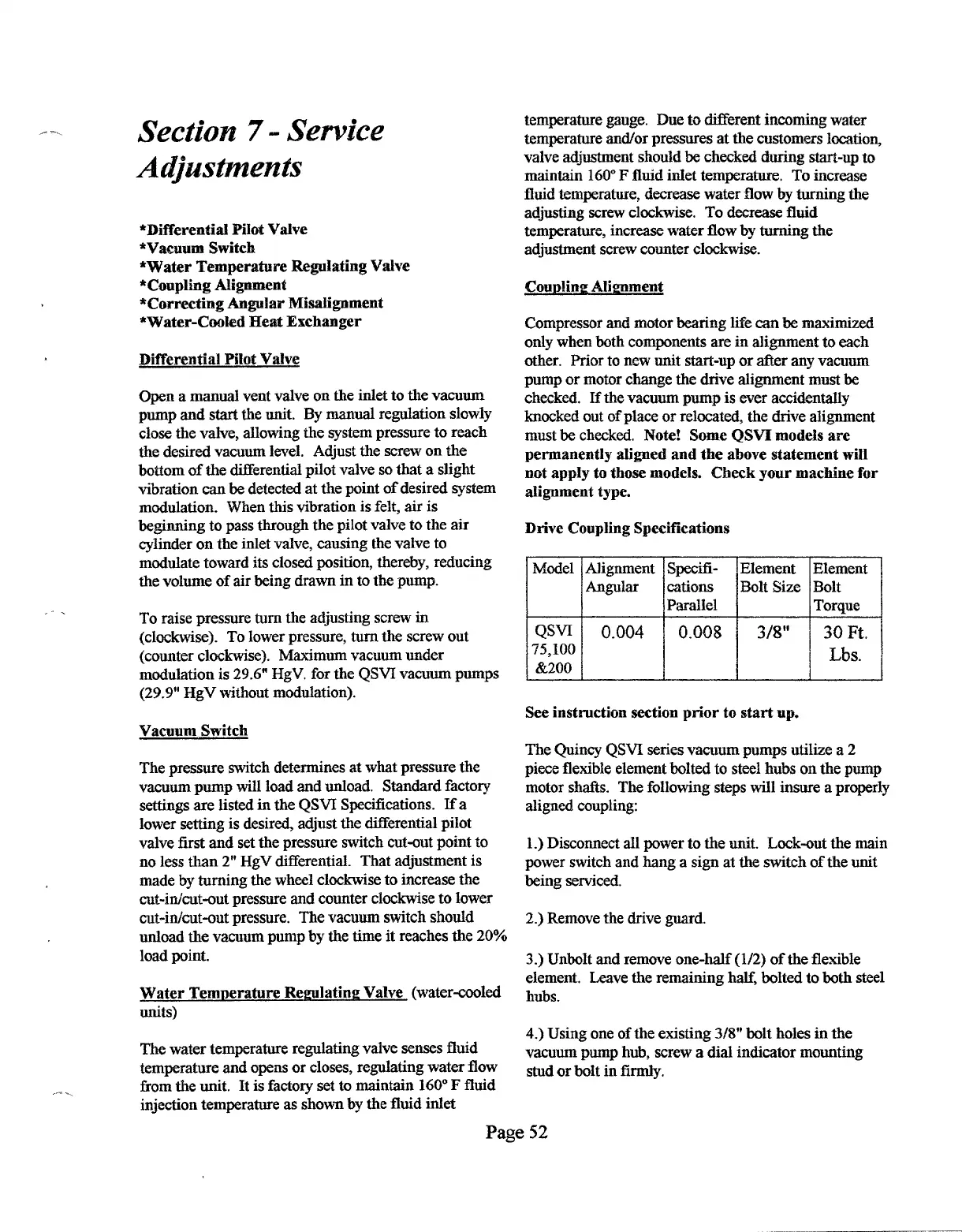
Drive Coupling Specifications
IModel IAlignment ]Specifi-
P
Element
Bolt Size
3/8”
3
Element
Bolt
Torque
30 Ft.
Lbs.
See instruction section prior to start up.
The Quiney QSVI series vacuum pumps utilize a 2
piece flexibIe element bolted to steel hubs on the pump
motor shatis. The following steps will insure a properly
aligned coupling:
1.) DiscoMeet aIl power to the tit. Leek-out the main
power switch and hang a sign at the switch of the unit
being serviced.
2.) Remove the drive guard.
3.) Unbolt and remove one-half (1/2) of the flexible
element, Leave the remaining half, bolted to both steel
hubs.
4,) Using one of the existing 3/8” bolt holes in the
vacuum pump hub, screw a dial indicator mounting
stud or bolt in firmly.
Page 52
 Loading...