Table of Contents
Introduction .................................................................................................................................................. 3
1. Radio Modem MR400 ............................................................................................................................. 4
Radio Part MR400 ......................................................................................................................................... 5
Modem Part ............................................................................................................................................ 5
3. MR 400 Connectors ...................................................................................................................................... 6
Antenna .................................................................................................................................................... 6
Serial Interface ....................................................................................................................................... 6
RS232, RS422 and RS485 Connectors..................................................................................... 6
Distinguishing Data Modules by Colour .......................................................................................... 6
Ethernet .................................................................................................................................................... 7
Analog and Binary Inputs and Outputs .......................................................................................... 7
Labelling ........................................................................................................................................... 7
Parameters ..................................................................................................................................... 7
Supply Connector ....................................................................................................................................... 8
Information LED .................................................................................................................................. 8
Service Connector ................................................................................................................................ 9
4. Table of Technical Parameters .............................................................................................................. 10
5. Dimensional Diagram .............................................................................................................................. 11
6. Labelling Radio Modems ....................................................................................................................... 12
7. Conditions for MR400 Operation ............................................................................................................ 13
Radio modem instalation and maintenence ................................................................................................ 13
Conditions of Liability for Defects and Instructions for Safe Operation of Equipment ............................ 14
Declaration of Conformity ......................................................................................................................... 15
Limitations of Use ...................................................................................................................................... 16
List of Figures
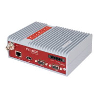
1. Radio modem MR400 .............................................................................................................................. 3
3.1. Service connector connections .......................................................................................................... 9
3.2. View of radio modem – description of connectors, model with DSUB (Canon)
connectors and with terminals .................................................................................................................... 10
5.1. Mechanical dimensions of MR400 .................................................................................................. 12
6.1. Serial codes of products ....................................................................................................................... 13
List of Tables
3.1. Table of data cable connections ........................................................................................................ 7
3.2. Table for distinguishing LEDs for RxD and TxD by colour ....................................................... 7
3.3. Table of Ethernet to cable connector connections ....................................................................... 8
3.4. Table of digital and analog input and output parameters ........................................................... 8
3.5. Table of service connector connections .......................................................................................... 9
4.1. Table of technical parameters ............................................................................................................. 13