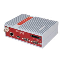
Ethernet
Connector RJ-45 for Ethernet 10BaseT and 100BaseT corresponds to the EIA TIA T568B standard. Informative
LED diodes indicate: Tx – output from CU Rx – input to CU 100 – if lit the 100BaseT LINK network is
indicated – indicates correctly connected F.D. link – indicates full duplex operation. A “straight” cable is needed
for connecting to the Ethernet network via the hub (repeater) or switch-hub (router). A “crossed” cable is mostly
used when just two devices are connected “back-to-back”. E.g. MR400 to MC100, MR400 to a PC, etc. The
following table contains connector connections and colours of conductors. For the crossed cable the order of
conductors on one side is the same as for the direct cable.
Table 3.3. Table of Ethernet to cable connector connections.
PIN Signal Direct cable Crossed cable
1 TX+ white - orange white - green
2 TX- orange green
3 RX+ white - green white - orange
4 — blue blue
5 — white - blue white - blue
6 Rx- green orange
7 — white - brown white - brown
8 — brown brown
Analog and Binary Inputs and Outputs
Labelling
Individual terminals of terminal blocks are labelled:
Connector A OUT - analog outputs
Connector A IN - analog inputs
Connector D OUT - digital outputs
Connector D IN - digital inputs From left to right: 1. input / output + 1. input / output - 0. input /
output + 0. input / output
- Terminal UP – From left to right: + - if a voltage of +2.4 to 15 V is brought to this terminal the radio modem
activates, firmware carries out the pre-programmed step according to settings in configuration (wake up from
sleep mode). Sleep mode is resolved by individual SW settings GND.
Parameters
Table 3.4. Table of digital and analog input and output parameters
2 × optically coupled digital output Bipolar solid state switch
(max. 30 V/500 mA)
Passive
2 × optically coupled digital input 2.4 – 15 V log. 1 0 – 2.4 V log. 0 Passive
2 × optically coupled analog output 0 – 20 mA Rz max = 250 Ohm Passive
2 × optically coupled analog input 0 – 20 mA/4 – 20 mA SW switchable (input
impedance 60 Ohm)
Passive
Analog inputs 0 and 1 have connected terminals ”-” (minus), which are galvanically isolated from the modem
GND. Analog outputs 0 and 1 have connected terminals ”-” (minus), which are galvanically isolated from the
modem GND.
Supply Connector
Terminals of this connector are labelled in the standard manner. Only DC voltage in the range from 10.8 to 15.6
V can be connected to the device. Voltages outside this range may damage the radio modem. Terminal PI
(power indicator): if the radio modem is fed from the MS2000 power supply information from this source is
7



 To Next Page