©
2000 RadioShack Corporation.
All Rights Reserved.
RadioShack and RadioShack.com are trademarks used by RadioShack Corporation.
OWNER’S MANUAL — Please read before using this equipment.
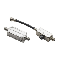
VU-120XR VHF/UHF/FM Antenna with Matching Transformer
Your RadioShack VHF/UHF/FM Antenna performs better than
standard antennas because of its special design features.
UHF Bowtie — delivers more of the UHF signal to your TV.
Since UHF signals are more difficult to receive than VHF sig-
nals, this antenna gives UHF signals the extra boost they need.
VHF/UHF Isolation Network — prevents the two types of TV
signals from interfering with each other. This results in cleaner
signals and a better picture on your TV.
BEFORE YOU BEGIN
Before you begin installation, read this manual and the sepa-
rate Consumer Product Safety Commission information sheet.
For your safety and convenience, plan each step of the installa-
tion and purchase the necessary hardware in advance. The
hardware required and the order in which you perform the steps
depend on the mounting and connection method you choose.
Warning: When you install your antenna, use extreme caution.
If the antenna starts to fall, let it go! It could contact overhead
power lines. If the antenna touches the power line, contact with
the antenna, mast, cable, or guy wires can cause electrocution
and death. Call the power company to remove the antenna.
Do
not attempt to remove it yourself.
ASSEMBLING THE ANTENNA
Assemble the entire antenna on the ground.
1. Use the supplied hardware to assemble the two main boom
sections, as shown. If necessary, lift one end of the main
boom so the crossover wires reach the threaded posts.
Note: To access slots or holes during assembly, move the
antenna’s elements out of the way as needed.
2. Use the supplied hardware to loosely attach one of the sup-
plied mast clamp assemblies to the main boom, as shown.
3. Attach the other mast clamp assembly to the cradle boom.
(Be sure it faces the same direction as the main boom’s
mast clamp assembly, shown above.) Fold out the two sets
of metal support straps on the cradle boom and attach
them to the corresponding holes on the main boom using
the two supplied 1
1
/
2
-inch screws and large wing nuts.
4. Press the supplied large end plugs into the main boom and
the cradle boom.
5. Pull the UHF bowtie’s two halves away from the main boom
until they lock into place. Then slide each half’s unattached
end over one of the antenna’s lead-in terminals (one for
each half of the UHF bowtie on each side of the boom).
Note: Both sections of the UHF/VHF isolation network
should remain parallel to the main boom.
CONNECTING LEAD-IN CABLE
TO THE ANTENNA
We recommend RG-6 cable and, if you prepare your own ca-
ble, a quality F-connector. You can also use 300-ohm flat, twin-
lead cable. (RadioShack carries a variety of suitable cables and
connectors.)
Large Wing Nuts
Splint
Threaded
Posts
Large Wing Nuts
Flat
Washers
1
1
/
2
-Inch
Screws
Crossover
Wires
U-Bolt
Mast Clamp
Backup Plate
Main Boom
Lock Nuts
Main Boom
Cradle Boom
Mast Clamp
Assemblies
Metal Support
Straps
Metal Support
Straps
UHF Bowtie Lead-In Terminal
UHF/VHF
Isolation Network
15-2154a.fm Page 1 Thursday, June 29, 2000 5:51 PM