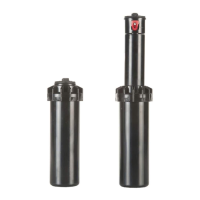
SO50 GEAR DRIVEN SPRINKLER
SETTING INSTRUCTIONS
NOTE: The SO50 is factory preset with a 40° arc setting, and includes a
pre-installed #1.5 nozzle.
CHANGING A NOZZLE
1. REMOVING THE NOZZLE RETENTION SCREW
Use the K-Key (A) or small flat blade screwdriver to remove the nozzle retention
screw (B) by turning counter-clockwise to remove or clockwise to re-install.
2. PULL UP THE RISER
Insert the K-Key (A) in the keyhole (C) on the top of the nozzle turret (D) and
turn the key 1/4 turn to insure that the key does not slip out of the keyhole when
you pull it up. Firmly pull up the entire spring-loaded riser to access the nozzle
socket (E). Hold the riser assembly with one hand.
3. REMOVING THE NOZZLE
With nozzle retention screw removed, the nozzle may be removed by either
turning on the water (wear safety glasses when using this method), or by
pulling outward on the nozzle wing (F) with a pair of needle-nose pliers.
4. INSTALLING A NOZZLE
Press the desired nozzle (G) into the nozzle socket (E). Make sure the nozzle
number is visible and the nozzle wing (F) are up. Then, re-install the
nozzle retention screw (B). NOTE: The nozzle retention screw is also a break-up
screw and used to adjust the distance of the spray.
SETTING THE ARC ADJUSTMENT
NOTE: The SO50 Gear Driven Sprinkler has a fixed right start and an
adjustable left stop.
1. POSITIONING NOZZLE TURRET TO ITS “RIGHT START”
Place your finger on the top center of the nozzle turret (D). Rotate the turret
counter-clockwise to the left stop to complete any interrupted rotation cycle.
Rotate the nozzle turret clockwise to the right start. This is the fixed side of the
arc. The nozzle turret must be held in this position for arc adjustments. The
right start does not change.
2. ADJUSTING THE RIGHT (FIXED) SIDE OF ARC
If the right side of the arc is not properly aligned, the sprinkler may spray in
areas not intended for watering such as driveways or adjacent properties. The
right side arc can easily be realigned.
OPTION 1: REPOSITION CAN ON THE FITTING
Turn the sprinkler can left or right to the desired position. This may require
temporary removal of the soil around the sprinkler to allow you to grip the
sprinkler can.
OPTION 2: REMOVE INTERNAL RISER A
SSEMBLY AND REPOSITION
Unscrew the top counter-clockwise and remove the internal sprinkler assembly
(J) from the can (K). Once removed with nozzle turret (D) at its right start,
reposition the riser assembly so that nozzle arrow points to the desired start
position. Replace the riser assembly back in the can and screw on the top. At
this point you have realigned the right arc stop, and you can adjust the left arc
to an appropriate setting.
3. ADJUSTING THE LEFT (VARIABLE) SIDE OF THE ARC
INCREASING THE ARC
Insert the K-Key (A) into the arc set adjustment slot (L). While holding the
nozzle turret (D) at the right start, turn the K-Key clockwise. Each full 360° turn
of the K-Key will increase the arc 90°. Adjust to any arc between 40° and 360°.
The K-Key will stop turning, or there will be ratcheting noise, when the
maximum arc of 360° has been reached.
DECREASING THE ARC
Insert the K-Key (A) into the arc set adjustment s
lot (L). While holding the
nozzle turret (D) at the right start, turn the K-Key counter-clockwise. Each
full 360° turn of the K-Key will decrease the arc 90°. Adjust to any arc between
40° and 360°. The K-Key will stop turning, or there will be a ratcheting noise,
when the minimum arc of 40° has been reached.
SPRINKLER INSTALLATION
1. INSTALL AND BURY
Do not use pipe dope. Thread the sprinkler on the pipe. Bury the sprinkler
flush to grade. NOTE: Gear driven sprinklers and pop-up sprays should not
be installed on the same watering zone.
2. INSPECTING THE FILTER
Unscrew the top and lift the complete sprinkler assembly (J) out of the housing
can (K). The filter is located on the bottom of the sprinkler assembly and can
be easily pulled out, cleaned and re-installed.
3. WINTERIZATION TIPS
When using an air compressor to remove water from the system please note
the following:
a. Do not exceed 30 PSI.
b. Always introduce air into the system gradually to avoid air pressure surges.
Sudden release of compressed air into the sprinkler can cause damage.
c. Each zone should run no longer than 1 minute on air. Sprinklers turn 10 to
12 times faster on air than on water. Over spinning rotors on air can cause
damage to the internal components.
SpA
SpA
A K-Key
C Key in Keyhole
C Key in Keyhole
B Nozzle
Retention
Screw
E Nozzle
Socket
D
Nozzle
Turret
J Internal
Sprinkler
Assembly
F Nozzle Wing
G Nozzle
Pressure Radius Flow
KPa Bars Meters L/M M
3
/H
207 2.0 7.0 5.3 .4
276 3.0 7.3 6.4 .4
345 3.5 7.3 7.2 .5
207 2.0 5.2 2.8 .2
276 3.0 5.2 3.0 .2
345 3.5 5.5 3.4 .2
207 2.0 6.1 3.4 .2
276 3.0 6.4 4.5 .3
345 3.5 6.4 4.9 .3
207 2.0 7.6 6.8 .5
276 3.0 8.2 8.0 .5
345 3.5 8.2 9.1 .6
207 2.0 8.5 10.2 .7
276 3.0 9.1 11.4 .8
344 3.5 9.1 12.5 .8
Nozzle
#1.5
#0.75
#1
#2
#3
DARD NOZZLE PERFORMANCE
ata represents test results in zero wind for the SO50.
st for local conditions. Radius may be reduced with
SpA
D Nozzle Turret
C Keyhole
L Arc Set Adjustment
SpA
Left
Stop
Right
Start
B Nozzle Retention Screw
K
Housing
Can
ENGLISH
RAIN SpA
via Kennedy 38/40
20023 Cerro Maggiore (MI)
Italy
TEL. +39 0331 514511
FAX. +39 0331 421375
www.rain.it
info@rain.it
L-13005122
Prestazioni
Performances
UGELLO
Nozzle
PRESSURE
bar
RADIUS
m
FLOW RATE
l/min
#0.75
2,07
2,76
3,45
5,5
5,8
6,1
2,8
3,0
3,4
#1.0
2,07
2,76
3,45
7,9
8,2
8,2
3,4
4,5
4,9
#1.5
Pre-installed
2,07
2,76
3,45
8,2
8,2
8,5
5,7
6,8
7,6
#2.0
2,07
2,76
3,45
8,8
9,1
9,4
7,6
8,7
10,2
#3.0
2,07
2,76
3,45
9,8
10,1
10,1
11,4
12,9
14,4