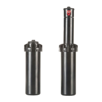
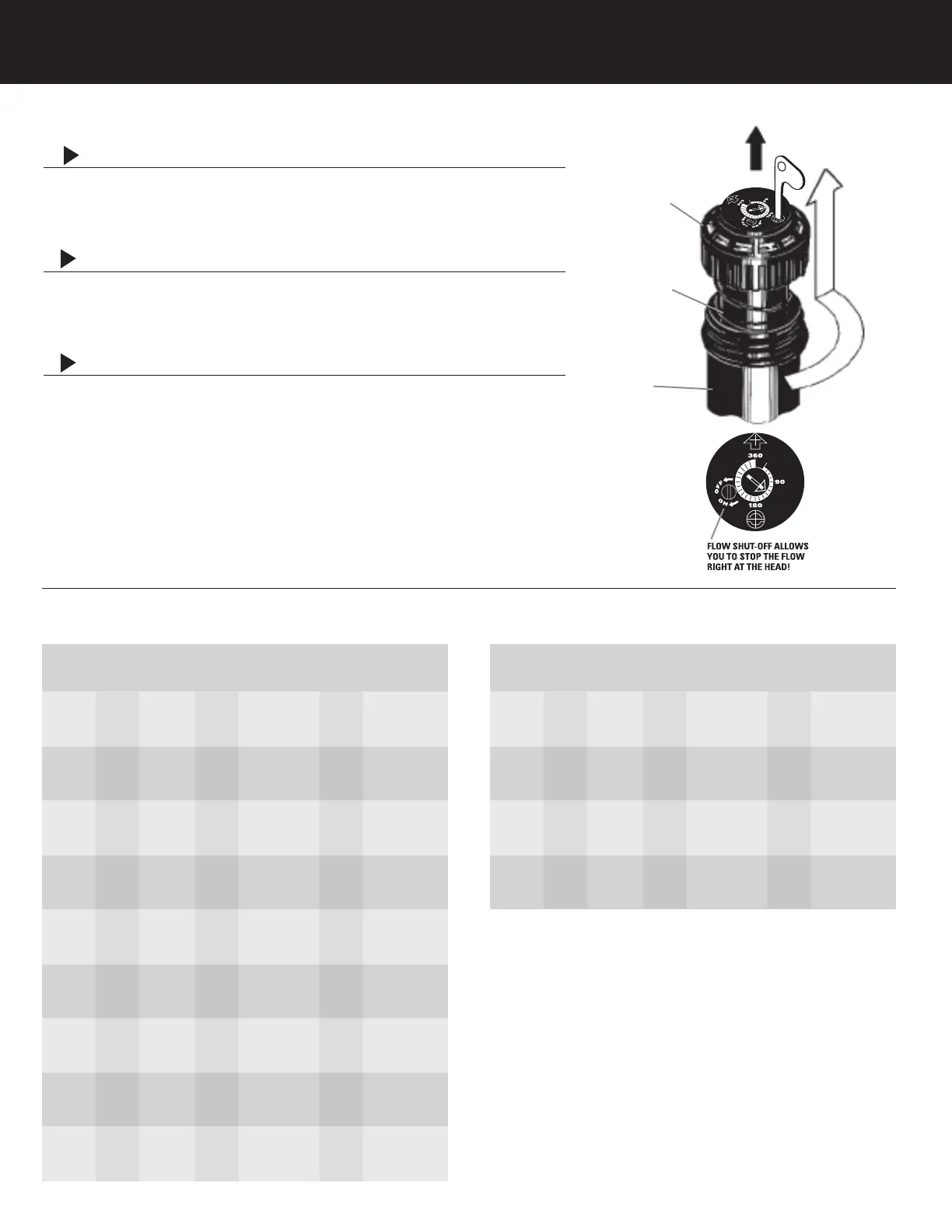
TWIST-LOCK
TOP
SPRINKLER
ASSEMBLY
HOUSING
CAN
STANDARD NOZZLE PERFORMANCE LOW ANGLE NOZZLE PERFORMANCE
SPRINKLER INSTALLATION
1
INSTALL AND BURY
Do not use pipe dope.Thread the sprinkler on the pipe. Bury the
sprinkler flush to grade. NOTE: Gear driven sprinklers and pop-up
sprays should not be installed on the same watering zone.
2
INSPECTING THE FILTER
Unscrew the top and lift the complete sprinkler assembly out of the
housing can. The filter is located on the bottom of the sprinkler
assembly and can easily be pulled out, cleaned and re-installed.
3
WINTERIZATION TIPS
When using an air compressor to remove water from the system
please note the following:
1) Do not exceed 30 PSI.
2) Always introduce air into the system gradually to avoid air
pressure surges. Sudden release of compressed air into the
sprinkler can cause damage.
3) Each zone should run no longer than 1 minute on air. Sprinklers
turn 10 to 12 times faster on air than on water. Over spinning
rotors on air can cause damage to the internal components.
S075 S GEAR DRIVEN SPRINKLER SETTING INSTRUCTIONS
METRIC
Pressure Radius Flow
KPa Bars Meters L/M M
3
/H
207 2.1 10.7 9.46 .57
276 2.8 11.0 10.60 .64
345 3.4 11.3 12.11 .73
414 4.1 11.6 13.63 .82
207 2.1 9.1 1.70 .10
276 2.8 8.8 1.89 .11
345 3.4 7.9 2.27 .14
414 4.1 7.9 2.65 .16
207 2.1 9.8 2.65 .16
276 2.8 9.8 3.03 .18
345 3.4 10.1 3.41 .20
414 4.1 10.1 3.79 .23
207 2.1 9.1 4.16 .25
276 2.8 9.8 4.92 .30
345 3.4 10.1 5.68 .34
414 4.1 10.1 6.06 .36
207 2.1 11.6 8.71 .52
276 2.8 11.6 9.46 .57
345 3.4 12.2 10.22 .61
414 4.1 12.8 11.36 .68
207 2.1
10.7 12.87 .77
276 2.8 11.0 14.38 .86
345 3.4 11.6 15.90 .95
414 4.1 11.9 18.17 1.09
207 2.1 12.8 15.52 .93
276 2.8 13.4 17.41 1.04
345 3.4 13.7 19.31 1.16
414 4.1 14.0 21.58 1.29
276 2.8 14.0 21.96 1.32
345 3.4 14.6 24.23 1.45
414 4.1 14.9 26.50 1.59
483 4.8 14.9 28.39 1.70
276 2.8 12.8 28.39 1.70
345 3.4 13.7 31.04 1.86
414 4.1 14.6 34.07 2.04
483 4.8 14.6 35.96 2.16
U.S.
Nozzle Pressure Radius Flow
PSI Ft. GPM
#2.5
Factory
Installed
Nozzle
#0.5
#0.75
#1
#2
#3
#4
#6
#8
METRIC
Pressure Radius Flow
KPa Bars Meters L/M M
3
/H
207 2.1 7.9 4.92 .30
276 2.8 8.2 5.68 .34
345 3.4 8.2 6.44 .39
414 4.1 8.5 7.19 .43
207 2.1 8.8 10.98 .66
276 2.8 9.1 12.49 .75
345 3.4 9.4 12.87 .77
414 4.1 10.1 15.14 .91
207 2.1 8.5 15.14 .91
276 2.8 9.4 17.79 1.07
345 3.4 10.4 18.93 1.14
414 4.1 11.0 22.71 1.36
207 2.8 9.1 22.71 1.36
276 3.4 10.4 26.50 1.59
345 4.1 11.3 29.53 1.77
414 4.8 11.6 31.04 1.86
U.S.
Nozzle Pressure Radius Flow
PSI Ft. GPM
#1 30 26' 1.3
40 27' 1.5
50 27' 1.7
60 28' 1.9
#3 30 29' 2.9
40 30' 3.3
50 31' 3.4
60 33' 4.0
#4 30 28' 4.0
40 31' 4.7
50 34' 5.0
60 36' 6.0
#6 40 30' 6.0
5
0 34' 7.0
60 37' 7.8
70 38' 8.2
30 35' 2.5
40 36' 2.8
50 37' 3.2
60 38' 3.6
30 30' .45
40 29' .5
50 26' .6
60 26’ .7
30 32' .7
40 32' .8
50 33' .9
60 33’ 1.0
30 30' 1.1
40 32' 1.3
50 33' 1.5
60 33' 1.6
30 38' 2.3
40 38' 2.5
50 40' 2.7
60 42' 3.0
30 35' 3.4
40 36' 3.8
50 38' 4.2
60 39' 4.8
30 42' 4.1
40 44' 4.6
50 45' 5.1
60 46' 5.7
40 46' 5.8
50 48' 6.4
60 49' 7.0
70 49 7.5
40 42' 7.5
50 45' 8.2
60 48' 9.0
70 48 9.5
 Loading...