FM10C 9
Jacks
2 RCA-type PC-mount jacks (J1,2)
1 2.1 MM power jack (J3)
1 F-type PC-mount jack (J4)
HARDWARE AND MISCELLANEOUS
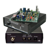
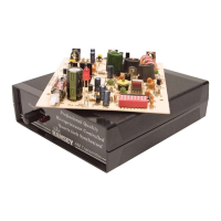
1 Ramsey FM10C Printed circuit board
1 38 KHz crystal [small silver cylindrical "can" with 2 small leads], taped
to a piece of paper.
1 PC board mounted DPDT switch
1 18 pin IC socket for BA1404
1 9-volt battery hold-down clamp
1 9-volt battery snap connector
1 Whip antenna w/screw
1 Plastic alignment screwdriver
1 Case with top, bottom, front, and back panels
4 4-40 x 3/13 (Short) Philips head screws
2 4-40 x 1-1/4 (Long) Philips head screws
4 Rubber feet
1 Button for DPDT switch
REQUIRED, NOT SUPPLIED:
9-volt alkaline or heavy-duty battery
Shielded stereo audio cables
Line-level output audio source (such as a tape deck or CD player)
OPTIONAL
LED "power on" indicator and 1K resistor
Audio switching-mixing accessories of your choice
External antenna, small gauge coaxial cable with F-connector (example
RG-6).
NOTES:
1. Selecting 18, 22, or 27 pf for C18; establishes the FM-band fre-
quency adjustment range. See “Choosing an Operating Fre-
quency.”
2. Selecting 180K, 220K, or 470K pf for R8; establishes the stereo pilot
level for the desired FM-band frequency to be used. See “Choosing
an Operating Frequency.”
3. R5 and R6 set the pre-emphasis of the transmitter. For 75 uS (USA)
use 15K ohm resistors. For 50uS (Europe) use 10K ohm resistors.