EasyManua.ls Logo

Ramsey Electronics FM100B User Manual

Ramsey Electronics FM100B
56 pages
To Next Page IconTo Next Page
Page #1 background imageLoading...
Page #1 background image
FM100B 1
Ramsey Electronics Model No. FM100B
Here’s the ultimate radio transmitter for all of you home brew
DJs out there! This all-in-one stereo transmitter has all the
features you will ever need for transmitting a school radio
station, around your yard, or even around the block.
Use the optional high power configuration for extra boost
when transmitting outside of the US!
2 Line inputs and one mic input-plus a built in mixer!
New Line output for monitoring your show!
PLL Crystal controlled for rock solid frequency
Left and right channel peak hold indicators and large LED frequency
display
Built in power supply, just plug it in! Now operates from 85-264VAC (47 - 63
Hz) without jumpers!
25 mW output standard, optional 1W configuration for operation outside
the US!
Auto AGC microphone muting function for cool talk-overs
Rugged steel enclosure for years of service
POWER
AUDIO
LEVEL
(L) (R)
P
R
O
F
E
S
SI
O
N
A
L
F
M
S
T
E
R
EO
T
R
A
N
S
M
I
T
T
E
R
Model FM100B
SELF
TEST
SETU P
FREQ
UP
FREQ
DOWN
MIC
AUTO
AGC
LINE 1 LINE 2
MIC
MIC
INPUT
MIC ON
FREQ LOCK
-18
-15
-12
-9
-6
-3
0
+3
+6
+9
-18
-15
-12
-9
-6
-3
0
+3
+6
+9
FREQUENCY
Question and Answer IconNeed help?

Do you have a question about the Ramsey Electronics FM100B and is the answer not in the manual?

Ramsey Electronics FM100B Specifications

General IconGeneral
BrandRamsey Electronics
ModelFM100B
CategoryTransmitter
LanguageEnglish

Summary

Introduction to the FM100B

Circuit Operation

FM100B Parts List

Project Assembly

A. Display Board

Install components on the display board, starting with resistors and LEDs.

B. Microphone Amplifier

Install resistors, diodes, capacitors, and ICs for the microphone amplifier circuit.

C. Audio Mixer

Install resistors and op-amps for the audio mixer and Auto AGC circuit.

D. Low Pass Audio Filters

Install precision 1% and 5% resistors and capacitors for audio filters.

E. Bargraph Peak Hold

Install diodes, op-amps, and capacitors for bargraph peak hold circuits.

F. Transmitter

Install resistors, capacitors, crystal, transistors, and diodes for the transmitter.

G. Transmitter Amplifier

Install capacitors, diode, inductor, resistors, and antenna for transmitter amplifier.

H. Microcontroller

Install capacitors, resistors, transistor, speaker, and IC socket for microcontroller.

I. Jacks and Switches

Modify and install push button switches, potentiometers, and audio jacks.

J. Power Supply

Install capacitors and voltage regulator for the power supply section.

K. Rear Panel Wiring

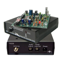
Install AC line cord, strain relief, fuse holder, and BNC connector on rear panel.

L. PC Board Mounting

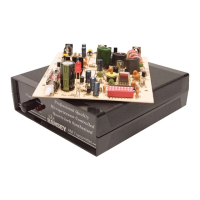
Mount main and front panel PC boards, connect jumper cables and Molex connectors.

M. Final Testing and Calibration

Test unit functionality, set frequency, adjust PLL, and verify LED indicators.

N. Final Case Up

Install rubber grommet, BNC cable, top case, screws, feet, and knobs.

Section Layout on Main Board

Display Board Parts Layout Diagram

Display Schematic

Main Board Parts Layout

Rear Panel Wiring Pictures

Troubleshooting

The Ramsey Kit Warranty

Professional FM Stereo Transmitter Kit Quick Reference Guide

Required Tools

Lists essential tools like soldering iron, pliers, and cutters.

Additional Suggested Items

Lists optional items such as magnifier and desoldering braid.

Related product manuals