FM100B • 36
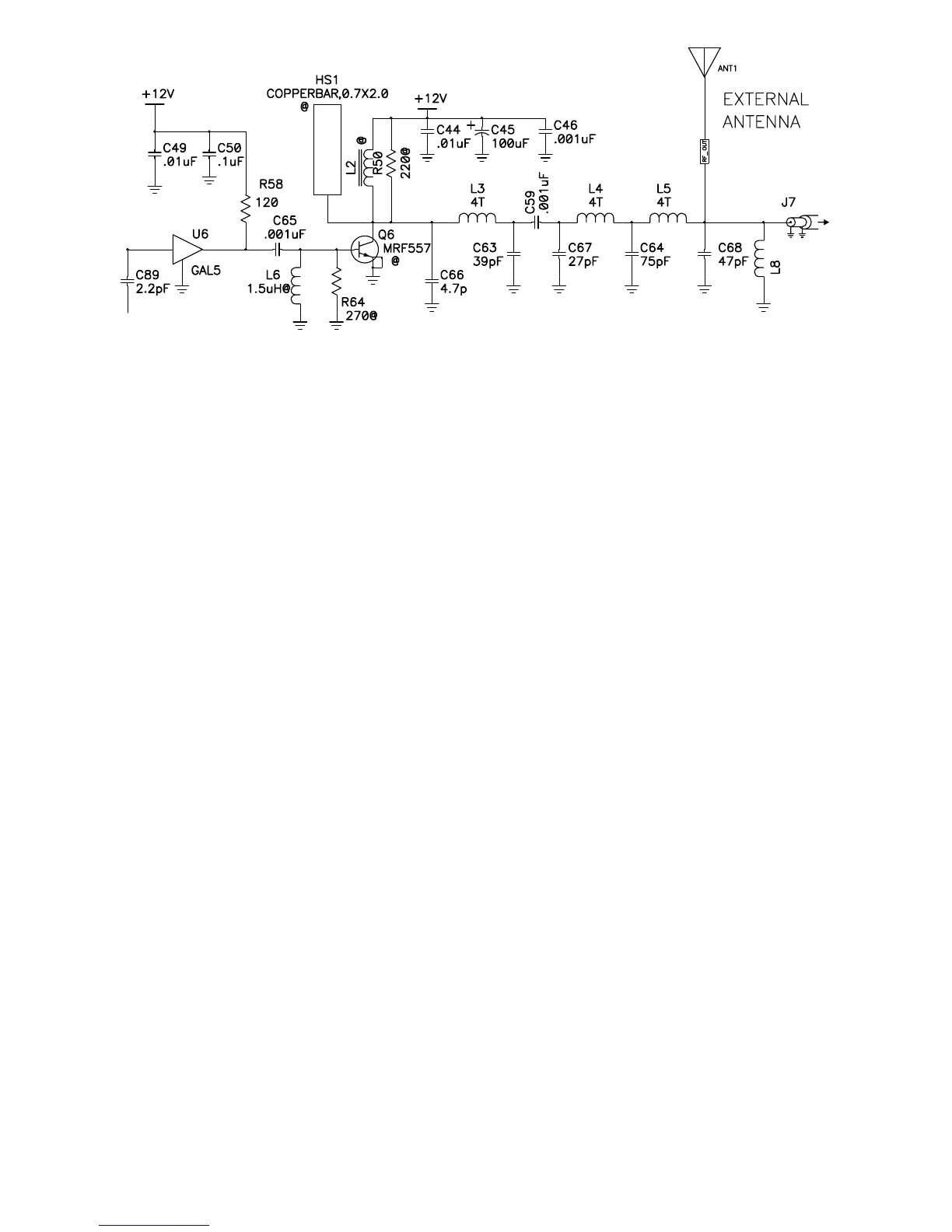
G. TRANSMITTER AMPLIFIER
This section covers the transmitter section of the standard FM100B. If you pur-
chased the High Power version, you will be installing the added components
right after these steps before you move on to the Microcontroller section. U6
has already been installed for you.
1G. Install C88, 0.01 uF capacitor (marked .01, 103 or 10nF).
2G. Install D9, IN4148 glass diode. Be sure to match the band on the diode
with the polarity band on the PC board.
3G. Install L7, 2.2 uH inductor (looks like a fat resistor with red-red-gold-
silver bands).
4G. Install R99, 100 ohm resistor (brown-black-brown).
5G. Install C89, 2.2 pF (marked 2.2).
6G. Install C49, a 0.01 uF ceramic capacitor (marked 103).
7G. Install R58, a 120 ohm large 1 Watt resistor (brown-red-brown). This
resistor will run a bit hot but don’t worry; this is normal and well within the
ratings of the component. Place the component in the holes in a stand-up
fashion to increase the part’s heat dissipation abilities. The body of the part
should be closest to U6 and off the circuit board by about 1/16” to avoid
physical contact with the amplifier.
8G. Install C50, a 0.1 uF ceramic capacitor (marked 104).
9G. Install C65, a 0.001 uF ceramic capacitor (marked 102).
10G. Install C66, a 4.7 pF or 5 pF ceramic capacitor (marked 4.7 or 5).
11G. Install L3, one of the pre-wound 4 turn inductors.
@ =Not Placed